Tool/software:
Hi all,
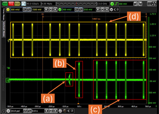
① When the test item related to LFPS of USB3.2 Tx Compliance Test is performed, it fails with “5G LFPS Peak-Peak Differential Output Voltage.”
② When checking the LFPS signal input to TUSB564 and the LFPS signal output from TUSB564 with an oscilloscope, there is no abnormality in the input LFPS signal, but there is abnormality in the output LFPS signal (the
amplitude of the first stage decreases).
(The waveform is probed by the terminals of C1/C9 and U2 of EVM. A personal computer is connected to P1 and a USB3 camera of our company is connected to P2.)
ch1: LFPS signal input to TUSB564, ch2: LFPS signal output from TUSB564
■About EVM settings
① Operating mode of TUSB564
GPIO mode (short pins 3 and 6 of JMP7 so that I2C_EN is directly connected to GND)
② EN
Short pins 2 and 1 of J4 so that they are pulled up by 1064_VCC
③ CTL0/CTL1
USB3.1 mode (CTL0=H, CTL1=L)
Short pins 2 and 1 of J2, and short pins 2 and 3 of J3
■Others
This may not be related to this issue, but
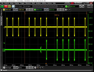
As shown below, the LFPS signal is output from the redriver approximately 8 ms after the LFPS signal is input to the redriver.
The device is different, but the contents are similar to the following.
(+) TUSB1046A-DCI: Compliance Test Fail - Interface forum - Interface - TI E2E support forums
The LFPS amplitude of the host output is not sufficient, the AC coupling value may be noy appropriate, etc.
I would appreciate any comments.
Best Regards,
Ryusuke