Because of the holidays, TI E2E™ design support forum responses will be delayed from Dec. 25 through Jan. 2. Thank you for your patience.

This thread has been locked.

If you have a related question, please click the "Ask a related question" button in the top right corner. The newly created question will be automatically linked to this question.

DC / AC converter - pwm part

Other Parts Discussed in Thread: UC2525A

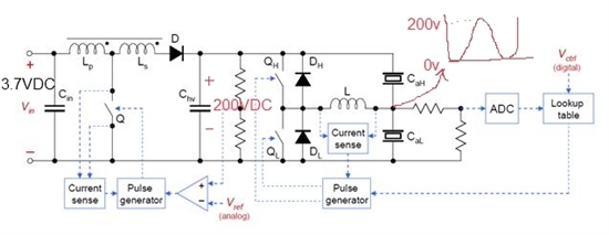
I have a circuit to magnify 3.7 VDC to 200 VAC, it has two steps, first a DC/DC flyback schematic to step up the voltage from 3.7 to 200 VDC and second a half bridge schematic to make the signal AC. I have two mosfets in the half bridge part which I want to do the switching and I have to switch them with high frequency (20~50 KHz or even more) and I want my output signal to have a frequency of (1~20 Hz). I am going to use the UC2525 to generate PWM signal, but I couldn't find any application note online to show me how I could use the IC.

anyone has any suggestion? would this IC do what I want?

  • It looks you would need a carrier signal for reference to generate 1 to 20Hz sinusoidal signal. Another concern is the load on the half-bridge will be floating and won't have common ground with the remaining system. Usually a transformer can be used to achieve this.

    I think the IC should do the work but there are system design considerations.

  • Could you describe more on how I could use the IC. the halfbridge is going to drive a piezoactuator. This is how my whole circuit would look like. Right now I am using a 555 timer for the switching of musfet Q. I have problems in switching the QH and QL. I tried to use a half bridge driver but the output frequency would be equal to the switching frequency. So I thought of using UC2525 which is a PWM controller. but I don't know how  should I use this iC since I couldn't find any application note or sample circuit for it. 

  • Your design needs a carrier signal to generate 1 to 20 Hz sinusoidal signal and you will need to design a feedback control using UC2525A to control the half-bridge to follow the carrier signal. If your carrier signal is a costant, the half-bridge will only output dc or something the same as the switching frequency.

    I believe your look-up table serves to get the sinusoidal carrier signal. the voltage on the switch node would still be switching pulses. You would need to filter out the switching pulses to get the sinusoidal wave.

    The current in the L should already be sine or close.

  • Hi

    Do you have an example design / application note for a 12VDC to 220VAC inverter design?

    Does it have to be in 2 steps (DC -DC and then make the sine wave)?

  • Actually the schematic above is the only thing that I have (without any description) and I am using that to implement the circuit. the problem is how should I do the switching? you mentioned something about look up table. Could you describe more how would it function and what I need to implement that?