LMG3100R017: How to connect AGND and HS in half bridge configuration

Part Number: LMG3100R017
Other Parts Discussed in Thread: LMG3100EVM-089

Tool/software:

Hi,

In the data sheet the connection of AGND of the high side GAN is to HS.
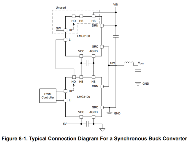
but in the Evaluation board (LMG3100EVM-089) it connect also to the SW
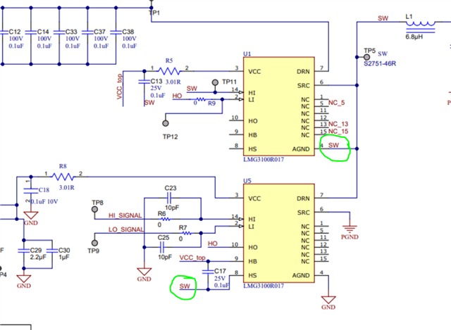
What is the right way to do this? like in the data sheet or the evaluation board?

how to connect the HS? in the data sheet it connect to VIN but in the evaluation it floating?

Best Regards,

Ariel Gershengold

  • Hi Ariel,

    On the LMG3100, the Agnd pin and the SRC pin are internally connected. When the LMG3100 is in the high side position in a half-bridge the SRC and Agnd pins will be connected to the switch node (SW). 

    The LMG3100 also includes a bootstrap diode to power the high side device. The HB pin is the bootstrap power rail and the HS is the reference ground for the bootstrap rail. The bootstrap reference ground will be connected to the high side device Agnd. This is also electrically connected to SRC & switch node (SW).

    Best,

    Kyle Wolf

  • So to make it clear. the connection the LMG3100EVM-089 is the right connection and the connection the datasheet is wrong.

    I understand it correctly?

  • Hi Ariel,

    They are both correct since the Agnd pin and SRC pin are connected internally in the GaN IC. The datasheet shows the nets connecting only using the internal (inside GaN IC) net connection. The EVM shows the net connection both internally (inside GaN IC) and external (on the PCB).

    Both are valid ways of making the connection. The connection in the datasheet will reduce the noise transfer from the SW to the HS pin.

    Best,

    Kyle Wolf