This thread has been locked.

If you have a related question, please click the "Ask a related question" button in the top right corner. The newly created question will be automatically linked to this question.

UCC21520: VCCI to GND Short

Part Number: UCC21520

Tool/software:

Hi,

The UCC21520 seems to have failed after the test was performed according to the procedure below.
It has previously failed with similar symptoms, so could you please review the circuit diagram? I have also attached the test procedure.
参考回路図・検査手順rev2 EN.xlsx

1. It was implemented as a pre-production prototype, and worked normally when the board was tested individually.
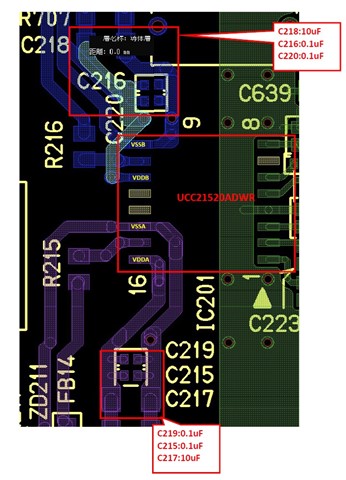
2. After the "UCC21520ADWR" mounting board was installed in the main unit, the impedance between VCC and GND of the "UCC21520ADWR"
    was low when the power was turned on, causing a failure.
    (It is not clear when the failure occurred after the board test)

We confirmed that no signal was input before turning on the power.
We also checked this circuit, but did not think there was any particular problem.
If you have any advice, it would be helpful to the customer.

Besr regards,
Hiroshi

  • Hi Hiroshi,

    Thank you for you question. Our team is out of office on Dec 24 and Dec 25 due to US holiday. Please also expect delay in our response during the holiday season period (from Dec 24 through Jan 2).  

    Thank you for your patience,

    Luowei

  • Hi Hiroshi,

    Thank you for your patience.

    Are there any local decoupling capacitors near the pins of the gate driver?

    Important ones here would be the VDDA/VDDB local decoupling capacitors. These should be placed as close as possible to the gate driver.

    Is there permanent damage of any of the components on the board?

    Looking forward to hearing back.

    Regards,

    Hiroki

  • Hi Hiroki-san,

    Thank you for your reply.
    I will check with our customer and get back to this thread.

    Hiroshi

  • Hi Hiroki-san,

    According to our customer, the decoupling (C215 - C220) is placed close to the power pins, and there is no permanent damage to other components.
    It may be difficult to determine why the power supply of this IC shorted out, but if you know anything, please advise.

    Best regards,
    Hiroshi

  • Hi Hiroshi,

    Thank you for following up.

    Sorry for the typo, I meant the VCCI decoupling capacitors!

    Regards,

    Hiroki

  • Hi Hiroki-san,

    Our customer explained that there are decoupling capacitors on all power pins.

    Best regards,

    Hiroshi

  • Hi Hiroshi-san,

    That is great to hear. 

    With the VCCI pin being shorted to GND, I just want to ensure that no datasheet absolute maximum specifications are being exceeded. Even if not intentionally exceeding the specs, transients from system noise or from start up operations may do so. 

    If there is any more information that the customer can provide such as any waveforms, layout, or detailed schematics, this will help me try to narrow down the source of this issue. 

    In general, these VCCI decoupling capacitors should be:

    • ~1uF bulk decoupling capacitor
      • Tantalum or electrolytic
    • ~100nF small high frequency decoupling capacitor
      • 25V, MLCC, X7R recommended
      • In parallel to bulk decoupling capacitor

    These capacitors should be placed on the same side as the gate driver <5mm away from the pins with priority to place the smaller capacitor closer to the driver.

    Regards,

    Hiroki

  • Hi Hiroki-san,

    I asked the customer, but unfortunately they said they could not provide a detailed circuit diagram or waveforms.
    However, I was able to obtain an excerpt of the layout.
    Looking at this diagram, it appears that there is decoupling for each of the two VCCI PINs.
    Normally, I think the two VCCIs are connected as short as possible and one decoupling is connected.

    It would be helpful to our customer if you could also let us know whether this is a problem or not.

    20240110参考回路図・検査手順rev3.xlsx

    Best regards,
    Hiroshi

  • Hi Hiroshi-san,

    Understood, thank you for letting me know!

    From the layout snippet, nothing seems to stick out as unusual. 

    Out of curiosity, is this occurring on multiple gate drivers or boards?

    Regards,

    Hiroki

  • Hi Hiroki-san,

    Thank you for your investigation.

    A similar failure has occurred once before, making this the second time (two ICs).
    We will first ask a testing agency to investigate the IV characteristics.

    Best regards,
    Hiroshi