This thread has been locked.

If you have a related question, please click the "Ask a related question" button in the top right corner. The newly created question will be automatically linked to this question.

BQ28Z610-R1: SoC gradually drops while battery is at full charge

Part Number: BQ28Z610-R1
Other Parts Discussed in Thread: BQ25792, GPCCHEM, BQSTUDIO, GPCRA0

Tool/software:

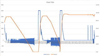
My device has two redundant batteries, each with its own BQ28Z610-R1 and BQ25792 charger. When the battery is fully charged and the charger remains on (supplying system load), sometimes the SoC of one battery will slowly drop (a few % per day) while the battery True remaining energy and battery voltage remain at full charge levels. SoC will drop to zero if we run long enough. This has been happening on a number of devices, but it's a slow process and I've not yet reproduced it on the bench so I can't provide a studio log.
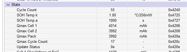
My question is what factors could make SoC deviate completely from True remaining energy? What other values should I log in the device to isolate this?
Batteries are running at normal room temperature, system load is constant but does include a pulsed current load where the battery supplies some of the current briefly (https://e2e.ti.com/support/power-management-group/power-management/f/power-management-forum/1355140/battery-is-charging-when-charge-status-1c-not-charging-000).

  • Hi.

    Can you share a log of this along with the .gg file.

    Do you have smoothing enabled?

    Regards,

    Diego

  • summary.bq.log.xlsx

    Diego, I was able to capture data with Studio when a battery was in the confused state. Attached files for battery 1 (with bad SoC) and battery 2 (normal) at 5 times. Note that these 2 batteries are in one unit and going through the charge/discharge stages together.

    A - Unit was running on the charger and battery 1 SoC has dropped to 91% while battery 2 stayed at 99%.

    B - Discharged to 4%/6%.

    C - Charged to 90%/99%.

    D - Discharged to 63%/70%.

    E - Charged back to 94%/99%.

    I've attached all the gg.csv files, but I see that the only change through the sequence is the cycle count. Battery 1 only counted one while 2 counted two cycles, so that may be a clue.

    The summary spreadsheet lists the bq.log data for both batteries at point A-E. Battery 1 is correctly tracking remaining capacity (which stays close to battery 2) but the Full Charge values are all too high, so SoC reads low. Since these batteries started with the same flash data, something in our usage is causing some gas gauges to recalculate full charge wrong.

    I'm hoping we can either prevent the full capacity miscalculation or have a way to reset it.

    4341.data.zip

  • Hi Jim,

    Thank you for sending over the data, we will begin looking into it. based on the initial .gg files of each of these batteries, it seems like battery 2 is calculating a Qmax update that is more relative to the capacity of the cell, while battery 1 is greater by ~150mAh. The SOC calculation of the gauge heavily relies on these values, so can you please confirm if there are any differences between the two batteries? I see that the cycle count of battery two is lower.

    Also, can you confirm if there was any relax time in between each of these steps?

    Regards,

    Anthony

  • The batteries started out identical - same golden gg.sv from our pack supplier. There are two batteries for redundant safety but they normally are in parallel through eFuses, so they stay together during drain, but may charge a bit out of sync since they have independent chargers.
    In the testing, the system load was always present, so the batteries were loaded as soon as the charger was turned off.
    I'm assuming the cycle count is different because battery 1 doesn't think it was fully charged, but I don't understand the criteria for that. They have seen the same sequence of charge/discharge cycles over their life of several months in lab testing.

  • Hi Jim,

    The cycle count is reliant on the percentage of accumulated discharge becoming greater than the Cycle Count parameter, which looking into the .gg file is 90%. So for step B, this will increase the cycle count, however for step D it is not enough discharge (alone) to increase the cycle count. Between each of these steps, is there any period of relax or do they occur one after another?

    Regards,

    Anthony

  • Does 'relax' mean neither charge nor discharge? If so, we can't guarantee a relax period. The unit may be turned on for many weeks with the charger turning on and off randomly. So the battery will go from charge to discharge without a relax.

  • Hi Jim,

    Understood, if there are long periods while the gauge is in function without any sort of relax period, then error can build up in the calculation due to a lack of a Qmax update. This can also lead to issues with the SOC representation at this time, however it is interesting that one cell in the system is working correctly while the SOC dropping is only seen in the other. When the SOC drops, you confirm above that the voltage does not change and that the charger is still applied at this time. Are there any changes in the FCC calculation at this time or is it just the remaining capacity that is dropping at this time?

    Regards,

    Anthony

  • Hi Anthony,

    I haven't been reading and logging FCC continuously in system, so I don't know whether it gradually increases or goes up in steps. I do know that the SoC decrements in 1% steps over time after full charge and with the charger supplying the system (and battery supplementing during the pulse load as described in my BQ25792 post). The remaining capacity remains pretty constant and close to the good battery, so the SoC drop is all due to FCC increase.

    At least some of the time, the battery with the low SoC has slightly higher voltage and supplies the supplemental pulse current, so it sees the most change in current. Is it possible that this small discharge/recharge cycling is confusing the FCC calculation? Is there a way to constrain the FCC calculation to not update under certain conditions (like when the voltage is above X)?

    Jim

  • Anthony,

    I added logging of RemCap, FullChgCap, TrueRemE, TrueFullChgE and ran a number of charge/discharge cycles, including some relax time. The ranges I saw for those values are:
    Battery 1 (low Soc): FullChgCap = 4840-4860 mAh, TrueFullChgE = 3340-3560 CWh

    Battery 2 (normal): FullChgCap = 4580-4580 mAh, TrueFullChgE = 3180-3340 CWh
    So the full levels of capacity and energy stayed too high on battery 1, and capacity didn't change much at all.
    I feel like the IT algorithm is trying to be too smart and getting fooled by our use conditions.
    Unfortunately, I have not yet observed the full capacity growing with the added logging, so I don't know when it occurred.
    Jim

  • Hi Jim,

    Sorry for the delay, would it be possible to share the log file of the two batteries with the RemCap and FCC being logged along with the .gg file of the gauge settings (for each situation if they are different)?

    Regards,

    Anthony

  • The gg's are the same as already posted. The attached log shows battery 1+2 on alternate lines. RemCap, FullChgCap labeled mAh to the right, followed by TrueRemE, TrueFullChgE labeled cWh.

    Changes in operation by line number (first column):


    573 charging

    9367 load on bat 1 only (bat 2 efuse off)

    35640 load off, bat 1 dead, relax

    41101 charge both batteries

    48661 charger off, load off

    52301 load on both batteries

    56799 load on bat 1 only (bat 2 efuse off)

    066667-100002 gap in log, but same state

    100019 charger on, no load

    104968 charge complete, no load (relax)

    107808 load on (bat 1 charges more because of the issue in my charger post)

    136013 charger off, load on both bats

    137175 charger on, load on

    mAh log.txt

  • Hi Jim,

    Thank you for sharing, we will begin to look through the data to see if there is a possible reason for this. Just to confirm as well, how was the chemID chosen in this situation? Was the GPCCHEM tool used?

    Regards,

    Anthony

  • Anthony, Answer from our battery pack vendor...

    The CHEMID was chosen for the cell used in your application, the BAK N2170CG
    CHEMID is 0x5432. The GPCCHEM tool was not used since the CHEMID was available for the cell.
  • Hi Jim,

    We have been looking into the data for Battery #1 which is described as the fault pack, however the current and SOC measurement can be seen below:

    With current being blue and the SOC being in orange, the only time it seems that the SOC drops when not intended is the last section of relax, where there is a roughly 2% drop from 97% to 95%. Can you please confirm where the issue is being seen in this situation or if something is being missed?

    Regards,

    Anthony

  • Anthony,

    I know this log doesn't show the growth in FCC, but I hoped it might give some clue to how the gauge sees our cycles. The large SoC drops occur over weeks of operation where the charger remains on. In some cases, the SoC drops below 50% when the battery is still full. Unfortunately, we discovered those after the fact and before I was logging FCC. I think the 97 to 95 drop in this log is just normal discharge by the always-on microcontroller load so that's not the problem appearing.

    I will continue to run a unit with the charger staying on to hopefully catch some FCC growth. Is there any other item I should log (It's not possible to run the Studio logging in situ).

    Jim

  • Hi Jim,

    Thanks for the clarification, if possible I would also log the ITStatus() register, the Qmax values seen below, and the temperature readouts (they can all be found in the DAStatus2() register) since the two biggest components that can cause change in the FCC are temperature and the Qmax. The ITStatus register will allow us to check that proper Qmax calculations are being conducted, with the Qmax values allowing us to confirm the generated values:

    Regards,

    Anthony

  • Anthony, I'll add those items to logging. It may take a while to capture the FCC growth with this new logging, so please keep the ticket open until I have more data for you.

    Thanks!

  • Anthony,

    Please confirm that the items marked are the ones I should log. I'm limited in logging space so I want to be sure. I am already logging temperature from Standard command 0x06/07. Is that the same as the TS1 value in DAStatuss2?

  • Hi Jim,

    I apologize for the confusion. Yes, the Temperature() value from the standard command should be OK here. For the Qmax values, please use the Qmax values from 0x0075, along with the bits from the GaugingStatus below:

    Regards,

    Anthony

  • Anthony, I've added gauging status to the logging. I'm confused by the definition of ITStatus2 in the TRM. When I run Studio and monitor i2c, it looks like the LStatus is in the 5th byte of data (address 0x44) which I would think is byte 'cc'. But the TRM says it's byte 'BB'. Is that a TRM typo?

    Edit: I checked another battery and the first 6 bytes of 0x74 are 0x03, 0x0E, 0x00, 0x00, 0x36, 0x04. So I don't know where Studio is getting the LStatus bits!

  • Hi Jim,

    What is the result of this if done with bqStudio from your end? I've set the LStatus to 0x04 and the read out and breakdown can be found below:

    Based on this, the TRM layout of the register seems to be correct. Just to confirm, is there any issues in what is being seen from GaugingStatus()?

    Regards,

    Anthony

  • Anthony,

    Gauging status is okay - my reads get the same data as Studio. But LStatus does not work like yours. Studio shows the correct register value, but the Advanced comm read is wrong. The i2c trace looks the same for both reads!

  • Hi Jim,

    I see what you mean, the advanced comm is returning the 0x0E (which is 14 in hexadecimal), which is the value being seen from the L Status register, however the bitwise representation of the register does not seem to reflect that.

    What is the value shown in the Update Status Register found in Data Memory -> Gas Gauging -> State?

    Regards,

    ANthony

  • Hi Jim,

    Thanks for confirming, is there any change in the registers bit representation if the device is reset? Also, was there a Qmax update that occurred in the field that would have pushed this to 0x0E?

    Regards,

    Anthony

  • I checked 10 batteries - all report 0E and RESET in Studio does not change that value. All show the same ITEN bit in the register view.
    We haven't done anything intentional to update Qmax. Can you say more about that - how it would push the register to 0x0E?
    And I assume you are still puzzled that 0x0E shows as just ITEN=1 in register view, correct?

  • Hi Jim,

    The gauge will push the LStatus to 0x0E if there is another Qmax update taken place after the learning cycle has been completed, which if this is the value of the LStatus when the golden image .srec is taken from the gauge.

    Would it be possible to share the .srec of the gauge so we can look into it on our end?

    Regards,

    Anthony

  • 4AMG_REV_02.srec.txt

    For some reason, the forum wouldn't let me insert an .srec file, so I just added the txt, but this is from Studio.

  • Anthony,

    Can you confirm that the incorrect presentation of LStatus bits is just a Studio bug? It looks like they convert the 4 bits to decimal and then interpret that as a hex value for the bit display. I turned gauging on and off, which toggles the 14 to 10 and back, and the ITEN bit goes red to green and back which is just a funny coincidence that 1110/1010 = 14/10 = 10100/10000 when incorrectly interpreted!
    Anyway, I will add those 4 bits to my logging and get that into our lab testing as soon as I can.

  • Hi Jim,

    Thanks for sending the .srec file, we will program one of our devices with it to see if we can produce the same result. The logging would be helpful to see if there is a Qmax update occurring that is pushing this value to 0x0E or if it is correct by the bitwise.

    Regards,

    Anthony

  • Anthony,

    I noticed that the full charge, full discharge and termination thresholds were set such that we would never meet them at either end. I reduced the max charge voltage due to the related BQ25792 issue, so we never reached 100% SoC. And we normally shut down before reaching 0% during discharge. If the gauge never sees these state changes, could that lead to the gradual drift in full charge capacity?

  • Hi Jim,

    If the gauge is in a shutdown state during the relax period after a discharge, then it could cause issues with the calculation since these calculations will not be done in shutdown. Can you please tell us why the shutdown is occurring at this time?

    Regards,

    Anthony

  • Anthony, I'm sorry my post was misleading. When I said "shut down" I meant that our device turns off before the battery drains to 0%, so the gas gauge normally never sees that low an SoC. The gas gauge itself is never shut down. So my question is what happens if the gas gauge never detects full charge or full discharge because those thresholds are outside the normal range of SoC? More specifically, if the device is powered all the time and the battery stays at 95% SoC and never meets the full charge threshold, but is affected by the pulse load I mentioned above, could it fool the IT algorithm.

  • Hi Jim,

    What is the typical range of SOC that the application will stay within? If there is not enough passed charge then there could be issues with Qmax Updates, which in the long run could accumulate error and cause issues with the SOC calculation.

    Regards,

    Anthony

  • Anthony, In the case where the SoC slowly drops, the charger is powering the system and the battery stays full, which is usually above 90%. But the full charge capacity keeps growing and SoC keeps dropping, so the problem must occur at SoC's well below 90%. Is there some way for my software to tell the gas gauge the battery is full so it won't keep recalculating?

  • Hi Jim,

    Was there ever a log file taken showing the declining SOC and increasing FCC? I think this could give us a better idea of why its occurring. Regarding the software, the FCC will recalculate if there is a simulation triggered, which typically happens at the end of relax, end of discharge, temperature changes by 5C.

    Regards,

    Anthony

  • Anthony, I don't have a log of the change yet. It takes weeks for the SoC to drop significantly and I have to fit logging into our lab schedule, so it may be a while. That's why I've been hoping to get something to try in the meantime.

  • Hi Jim,

    Understood, do you have any .gg files from the past before and after this issue happened? This could allow us to look at the resistance tables at this time as well.

    Regards,

    Anthony

  • Anthony, Here is the original .gg used in all the packs when new. 5000.BAK.2022.03.22.csv
    Compare this to two files from the zip in my original post:
    33111.2.A.gg.csv - "Good" battery where the full capacity hasn't gone up. Lots of differences in the resistance data.
    33111.1.A.gg.csv - "Bad" battery where full capacity has grown. Resistance data almost matches the original.

  • Hi Jim,

    Thanks for sending that over, E2E is currently not allowing me to see the previously sent 33111.2 and 33111.1 files, so if you could please resend them that would be great.

    However, this allows us to know that there are some differences in the resistances between the two packs, which will be helpful when we analyze the log. Can you please run the GPCRA0 tool at this time as well and share the results? This can give more insight to the resistance differences as well.

    https://www.ti.com/tool/GPCRA0 

    Regards,

    Anthony

  • The GPC instructions sound like we need precise external measurement of current and voltage while the battery is installed, which will be difficult. Will it work just be logging the gas gauge ADC data or is that not accurate enough?

  • Hi Jim,

    Thanks for sharing, the gauge ADC values for current and voltage should be ok here.

    Regards,

    Anthony

  • Anthony, GPC results are attached. Lots of errors I don't understand. The ChemID in config.txt matches what Studio reports and our vendor told me.

    6204.amgis1-report.zip6204.amgis2-report.zip

  • Hi Jim,

    Would it be possible to share the files inputted to the GPCCHEM tool so we can look them over?

    Regards,

    Anthony

  • Hi Jim,

    Thanks for sending. It seems like the tool is having issues since the Ra Flags are not set to FF or FF55. The flags should be set to this when the chemID is programmed to the device, but might change if any testing has done. In the inputted .gg file, these are currently set to 0. Can you please try programming the chemID again and pulling the .gg to make sure that these flags are set to the right value?

    Regards,

    Anthony

  • Anthony, Do I program the ChemID just using Advance Comm?

  • Hi Jim,

    This has to be done through the Chemistry tab in bqStudio. Once the chemID is found in the list, press Program Selected Chemistry:

    Regards,

    Anthony