This thread has been locked.

If you have a related question, please click the "Ask a related question" button in the top right corner. The newly created question will be automatically linked to this question.

BQ40Z50-R2: Selecting right Charger IC for 4S-10S Li-ion Battery Pack

Part Number: BQ40Z50-R2
Other Parts Discussed in Thread: BQSTUDIO, BQ25720, BQ25756, BQ40Z50, BQ41Z90, BQ25750, EV2400

Tool/software:

Hi Everyone,

I’m seeking an expert advice here on selecting a charger IC as per the below requirements:

I’m working with a 4S Li-ion battery pack with a BMS that includes the BQ40Z50-R2 fuel gauge and a dedicated microcontroller for monitoring. I’m planning to design a charger that utilizes the Advanced Charging Algorithm feature of the fuel gauge.

My current plan:

I will use microcontroller on the charger to poll ChargingCurrent and ChargingVoltage data from the BMS and set the charger output accordingly.

The charger will have two independent output channels, each managed by a dedicated charger IC. Final product will include two charger ICs, with the one microcontroller for monitoring and managing both charger ICs.

For the power supply, I plan to use a market-ready AC-DC module, such as the MEANWELL LOP-300-24, to provide 24V DC to each charger section.

I also have a couple of questions:

Memory Storage: Do most charger ICs store programmed parameters (e.g., set via BQStudio), or will I need to reprogram these parameters through the MCU after every power cycle?

Compatibility with other Batteries: My goal is to make the charger versatile enough to handle other batteries that may not provide ChargingCurrent/ChargingVoltage information or lack SMBus/I2C communication altogether. For that situation, I plan to configure the charger output to a limited current (e.g., 3A).

Please advise on the charger IC selection my choices were BQ25756, BQ25720 and also let me know what to do you think about my approach here.

Thanks

  • Hi Rohit,

    BQ40Z50 is only for up to 4S battery pack. To stack more cells in series, you would need a different protector gauge combo like BQ41Z90.

    TI charger's have state machines that make decisions based on I2C or SMBus register settings.  The register settings reset to default if the WD timer expires (can be disabled) or full POR (meaning both input power and battery fall below their respective UVLO voltages). 

    BQ25720 can only charge up to 4S and uses SMBus communication.  Charge is not default enabled so the software must write to it to enable charging.  Also, it does not provide termination so the BQ40Z device must monitor the charge current and then, through host software, tell the charger to stop charging.  The BQ25720 is an NVDC charger meaning it can provide a minimum system voltage even when the battery is fully discharged.

    BQ25756 can charge up to 14S and uses I2C communication.  Charge is default enabled and termination feature is enabled.  However, with system tied to battery, the charger cannot distinguish between charge current and system current so charge termination can not be reported even if the battery is fully charged.  Default charge current can be set by external resistor. 

    BQ25756 or one of the BQ25750 family members is a better fit if you plan to charge above 4S.

    Regards,

    Jeff 

  • Hi Jeff,

    Thanks for the above clarification.

    As per your suggestion, I have decided to go with BQ25756.

    Also, it would be great, if you could extend the explanation of below quoted part.

    However, with system tied to battery, the charger cannot distinguish between charge current and system current so charge termination can not be reported even if the battery is fully charged.

    As mentioned earlier, I am planning to charge the batteries which doesn't have smart BMS for e.g. BQ40Z50 which generally shares the data with charger. In that case if I have to set the charging current & voltage using external resistor which will work as in default mode if no communication is present in the battery. I also have a doubt if it's possible to increase the charging current and change the charging voltage using registers bits & microcontroller which was set via external resistor as a default configuration, I am putting an example here for better understanding e.g. if I have two 4S Li-ion batteries, one shares the charging current & volage data with our charger and second battery which doesn't have that sort of information/feature or capabilities to share any information with the charger. So, in that case if I have set the 16.8V and 3A using external resistor as default, can I increase the charging current to 6A and charging voltage to 16.8V, 16.6V or 16V via resistor bits using microcontroller of charger.

    Default charge current can be set by external resistor. 

    Thanks & Regards,

    Rohit

  • Hi Rohit,

    Regarding the termination current, if the external resistor measures both battery charger plus system load current, the charger may terminate charge early because the sensed current includes system current as well.

    Regarding changing ICHG and VREG:

    1. ICHG resistor sets the max charge current that can be set in the ICHG I2C register if EN_ICHG_PIN bit = 1.  To set higher charge current, the host must first write EN_ICHG_PIN=0 and the I2C to the ICHG register. 

    2. VREG resistor divider sets the regulation point VREG= (1+RTOP/RBOTTOM)*VFB_VREG where the host can I2C write to change VFB_REG register as shown below:

      Alternatively, the resistors could changed dynamically, for example, with a parallel resistance and FET to GND or a digital potentiometer to change ICHG or VREG.

    Regards,

    Jeff

  • Hi Jeff,

    Thanks for the above clarification.

    Regarding the termination current, if the external resistor measures both battery charger plus system load current, the charger may terminate charge early because the sensed current includes system current as well.

    I am still not able to understand the "system load current" here, can you please simplify this for me?

    I also understood the part where charger may terminate the charge early because the sensed current includes system current, so what would be workaround for this.

    VREG resistor divider sets the regulation point VREG= (1+RTOP/RBOTTOM)*VFB_VREG where the host can I2C write to change VFB_REG register as shown below:

    I also have multiple doubts related to this:

    • Does RTOP needs to be 249kΩ as shown in the image or I can use any value as per my choice? 
      • Alternatively, the resistors could changed dynamically, for example, with a parallel resistance and FET to GND or a digital potentiometer to change ICHG or VREG
      • As per your multiple suggestion, which would be reliable the way of controlling charging voltage & current, while on-going battery charging cycle.
        • as mentioned above i was planning to use register bits for ICHG & VFB_VREG because this seemed easier to me.
    • Regarding TS pin
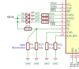
      • I dont have option to share the battery temperature information to charger's TS pin in that case, can i just disable the TS pin via connecting it to PGND as per below attached image from datasheet  or i have to fake the thermistor signal as shown in below schematic image.

    Please advise.

    Thanks & Regards,

    Rohit

  • Hi Rohit,

    Regarding system load current, the charger sees any load connected after the battery charger's current sense resistor as charge current.  So, if the charger's termination current is set to 100mA and the system load current is > 100mA, the charger will not be able to termination.  In that case, I recommend disabling charger termination using the EN_TERM bit (if available) or setting termination current very low.  Then I recommend using the BQ40Z to measure battery current only through its sense resistor.  The host software can then monitor the BQ40Z to know when charge current < termination current (set higher than charger termination current) and can tell the charger to stop charging.

    Regarding RTOP, it does not have to be exactly 249kohm but needs to in that range +/- 249kohm.  If too large, the leakage current into the FB pin dominates and changes the regulation point.  If too low, the battery discharges too quickly.  Using the I2C register is the easiest way to modulate the output voltage and/or charge current.

    Regarding TS pin, you can hardware disable using a resistor divider that sets V(TS) to the mid point of the V(REGN).  Or the host can disable TS function using the EN_TS bit.

    Regards,

    Jeff

  • Hi Jeff,

    Thanks for your detailed explanation.

    I have a doubt if EV2400 will have issues in communicating with BQ25756, if a micro-controller is present on the same SCL & SDA lines. If yes, then what would be the workaround.

  • Hi Rohit,

    The EV2400 and BQSTUDIO do not auto read/write unless the user enables the auto read function (not recommend).  So as long as the user does not perform a read/write to the same address at the exact same time as the micro-controller, there should not be a problem.

    Regards,

    Jeff

  • HI Jeff,

    I sincerely thank you for your support.

    Regards & Thanks

    Rohit