This thread has been locked.

If you have a related question, please click the "Ask a related question" button in the top right corner. The newly created question will be automatically linked to this question.

BQ24600

Other Parts Discussed in Thread: BQ24600, BQ24610, BQ24610EVM

Dear All


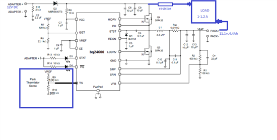
I am using BQ24600 to charge my battery pack of 11.1V4.4Ah.

Problem is my battery pack is an ordinary one no 'smart'ness :-(

Now what will I do with TS (pin No.4)  pin? Can I just ground it?

Hope I can discharge my battery while it is being charged?!?!


Plz clear my doubt


Love

Nikhi

  • If you don't want to use TS pin, you can add a 100k/100k resistor divider on TS pin between VREF pin and ground.

    I don't understand the requirement of "discharge my battery while it is being charged".  Would you give more infomation about that? We can use datasheet application circuit or EVM schematic as reference to talk about it.

  • Thanks for the help Wang!!!

    This is the very first time I am working on power modules.

    Please find the circuit diagram(Modifications I am planning is in blue blocks.).

    • My doubt/ question was, Can I connect the adapter to my load directly while charging my battery pack.
    • Could you please tell me the purpose of giving a voltage(VREF/2) to TS pin?
    • Is it ok if i connect the digital and analog ground through a zero ohm resistor and connect the ' pwrpad ' pin to any one of the grounds?


    Thanks for the help


    love

    Nikhi


  • 1. I think you need a system power selector charger: bq24610. That charger can automatically switch the system load connection. The adaptor can charge battery and support load simultaneously.

    2. When TS pin voltage is in a right range, the charger can start charging. Please check the datasheet spec table.

    3. You can connect the digital and analog ground through a zero ohm resistor near the 'pwrpad' and connect the ' pwrpad ' pin to any one of the grounds

  • Thanks a lot !!!

    CAn I use the application 'Typical' ckt given in the datasheet??

    Do you have the BOM for this( I couldn't find it in the web site) ? Any replacemnt for the given mFETS?


    thanks again

    nikhi


  • The bq24610EVM user's guide gives a schematic and BOM: http://www.ti.com/litv/pdf/sluu396a 

    You also can use a calculation tool to calculate or change component value:  http://www.ti.com/litv/zip/sluc175d

  • Thanks a lot for the post.


    I had a look at the document. There are some modifications in the evaluation module,so do you think the Typical application circuit is good enough or should I go for the modified version(EVM) ?

    Could yoy please explain to me what LED indication is this other than Status/PG?


  • I think you can use an EVM to evaluation your system first. And then, you can decide the final modification.

    The /ACDRV and /BATDRV LED can indication the /ACDRV and /BATDRV status. So, you can know the system load is connected to input adaptor or battery.