This thread has been locked.

If you have a related question, please click the "Ask a related question" button in the top right corner. The newly created question will be automatically linked to this question.

LP3966: LP3966 not hold current load

Part Number: LP3966

Tool/software:

Hello,

Based on a design produced some time ago, our customer is currently reporting problems with the 3.3V LP3966 regulator's load handling. Voltage only drops when microcontrollers start up, so they are constantly rebooting. The output current required by this regulator is around one hundred mA, well below the LP3966's maximum capacity of 3A.

We have very recently repaired a board by changing the regulator and the output decoupling capacitor.

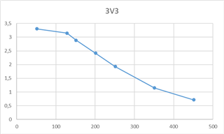
I was able to make the following measurements after changing the components :

3V3_BENCH Load

3V3_BENCH

Consumption on primary 12V

Unloaded

3.306 V

44 mA

93 mA

3.304 V

90 mA

305 mA

3.303 V

183 mA

500 mA

3.303 V

272 mA

1 A

3.303 V

502 mA

2 A

3.000 V

566 mA

These measurements seem to be good, and the oscilloscope measurements didn't show any faults either.

Here's the schematic implementation and routing of this regulator on the : 

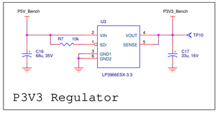
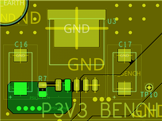
The implementation seems to be correct with regard to the datasheet recommendations.

-> So what could make the regulator malfunction on the power supply? And why are there now regulators that no longer hold the load? 

Design problem (thermal brake too weak?)
Output overload/short-circuit (yet internal protection in the controller?)

Thanks a lot for your help,

Best Regards,

Louis

  • Hi Louis,

    I'm unsure of the issue that your customer is reporting because they have only provided the data for a "good" test after replacing the device. Please provide a description of the issue they are seeing, and it would be helpful if they can provide waveforms showing the "voltage drop" when the microcontroller starts up.

    5V -> 3.3V at 100mA is only 170mW, which is not a thermal issue, and the loading level is far from the current limit, so I don't suspect an overload protection issue. What it sounds like (without knowing exactly what the issue is) is that the microcontroller is pulling a larger current during startup, and the load transient performance of this device is not sufficient to respond quickly enough and so the output voltage droops. I'll need to see some more data to verify this.

    Regards,

    Nick

  • Hello,

    Thank you very much for your feedback. I will check with my customer to get more data.

    As far as power output is concerned, I find it hard to believe that there's a problem here either. Especially as the component is protected against temperature, short-circuit...

    I'll keep you informed

    Thanks & Regards,

    Louis

  • Hi Louis,

    Sounds good. I'll await you reply.

    Regards,

    Nick

  • Hello,

    I have just taken the following measurements : 

    base load in the circuit (mA) 51
    Load Apply (mA) Total Load (mA) 3V3 5V power (W) Dissip Power (W)
    0 51 3,305 4,993 0,17 0,09
    77 128 3,149 4,991 0,40 0,24
    100 151 2,889 4,991 0,44 0,32
    150 201 2,415 4,99 0,49 0,52
    200 251 1,931 4,989 0,48 0,77
    300 351 1,15 4,987 0,40 1,35
    400 451 0,715 4,986 0,32 1,93

    The oscillograms associated with the measurements are attached.Oscillogram.zip

    For information the 5V regulator is the LM2677S-5.0 with 260 kHz switching frequency which we can see clearly on the graphs

    Let me know if you see a potential source of the problem

    Thanks & Regards,

    Louis

  • Hi Louis,

    This looks like a thermal issue after all. I noticed in the screenshot of the PCB layout that the thermal pad is only connected to the ground pour at the 4 points that I highlighted below and is otherwise isolated. Am I correct? If so, the on-board heatsinking is severely limited and the thermal performance will be much less than the datasheet metrics suggest. 

    Regards,

    Nick

  • Hi Nick,

    Thank you for your comment. Indeed, the thermal pad is only connected to the ground pour at the 4 points that I highlighted. However, there are more than 20 board with this design that are fully functional. Only 2 boards have had this failure, and we think it's possible that we've come across a batch of faulty components. What do you think?

    I'm not sure it's a thermal problem, as the faulty component doesn't heat up at all + it's thermally protected.

    In any case and for future projects, it is recommended that no thermal brakes be applied to thermal pads? Does this cause any problems for component assembly and/or removal?

    Thanks & Regards,

    Louis

  • Hi Louis,

    It's unlikely that the devices were faulty since they are tested for functionality before shipping. 

    I'm not sure it's a thermal problem, as the faulty component doesn't heat up at all + it's thermally protected.

    When you pull 500mA+, the device doesn't heat up at all? That doesn't sound right regardless of whether the output voltage was maintained because the power dissipation would still be high, and in fact the power dissipation goes up when the output voltage sags (assuming that the input voltage does not sag). The thermal protection does not prevent the device from heating; the channel is closed when the device heats excessively (it's usually around 160C ~ 175C junction temperature that the device shuts down). 

    In any case and for future projects, it is recommended that no thermal brakes be applied to thermal pads? Does this cause any problems for component assembly and/or removal?

    Yes, the recommended layout is a continuous connection for the thermal pad with thermal vias under or near the thermal pad. I do see thermal vias near the device in the layout, but with the limited connections the heat cannot easily leave the thermal pad. There won't be issues with assembly, but removing the device is certainly more difficult when the board-level heatsinking is improved. With that said, it's usually not much of an issue if you have access to a heat gun to remove the devices. Some of our EVMs are highly thermally optimized and it can be difficult to get the device off the board, but in many applications there isn't enough board space available to achieve such a high level of board-level heatsinking, so I wouldn't consider it an issue. 

    Regards,

    Nick

  • Hello,

    Thank you for all this information.

    If I understand correctly, it's possible that the component has overheated and faulted the output even if only a small current is drained?

  • Hi Louis,

    Yes. The junction temperature will rise a lot more than expected with the reduced board-level heatsinking. However, what is not clear to me is why the output voltage looks to be "sagging" when the load increases (heating the device); this is a CMOS device, and for CMOS devices the thermal shutdown is usually an abrupt turn off instead of the sagging that is seen in the data they collected. The waveforms they provided seem to show that the output isn't turning off, but the time scale is pretty small (2us/div or 800ns/div), so it's unclear whether the output is turning on and off (cycling in and out of thermal shutdown) or if the output has just sagged. If they can collect some more measurements showing the output voltage on a DC coupling and a more zoomed-out time scale (e.g. 10ms/div) at an elevated load current that sagging has been observed, that would help assess the issue.

    Regards,

    Nick

  • Hello, thank you very much for all this information. Unfortunately, we have no more faulty boards. If ever the fault reappears, I'll take measurements again.

    Regards,

    Louis

  • Hi Louis,

    What happened to the boards that were faulty? 

    Regards,

    Nick

  • Precisely, we don't have much information on the cause of the fault, as the boards are at our customer's site. Apparently, no manipulations were performed before the 3V3 was found to be at the wrong voltage (too low).

  • Louis,

    Understood. I'll close this post and if you need further assistance, please create a new post. 

    Regards,

    Nick