This thread has been locked.

If you have a related question, please click the "Ask a related question" button in the top right corner. The newly created question will be automatically linked to this question.

TUSB1046A-DCI: Traces

Part Number: TUSB1046A-DCI
Other Parts Discussed in Thread: TUSB501

Tool/software:

Hello,

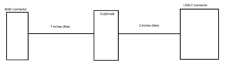
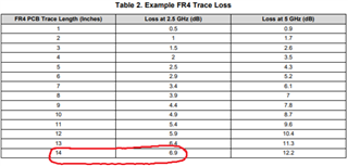
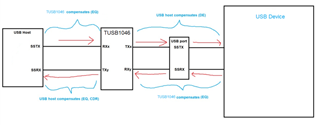
I am using an MXM card and the DP traces in the are max 2 inches. On the mother board how long can my traces be from the MXM connector to the cross point switch with redriver TUSB1046AI-DCI? Is 8 inches okay or a total of 10 inches? We are using mid loss material but assume worst case as FR4 so we can only be better.

Thanks,

Divakar

  • Hi Divakar,

    Can you show a block diagram of the system so I can get a better idea of which length you're asking about? Right now I'm assuming it looks like this:

    We have guidelines in the datasheet for how a system might look with the TUSB1046 in the signal path (12" before and 2" after the re-driver). Note that these are not requirements for all systems, this is only an example of what we have seen work in the past:

    Best,

    Shane

  • Thanks,

    in the block diagram you drew it is 2 inches inside the MXM card and what can it be max to the TUSB1046. Can it be 8 inches so the total is 10 inches from source of DP to TUSB1046.

    Divakar

  • So DP source to TUSB1046 is 10 inches < 12 inches in your design guide, I still have 14 dB of compensation from TUSB1046 to the display correct? I expect the length the USB connector no longer than 6 inches.

  • Hi Divakar,

    Can it be 8 inches so the total is 10 inches from source of DP to TUSB1046.

    Yes 10in seems reasonable between the DP source and the TUSB1046. High speed signals are sensitive to layout routing, # of connectors, # of vias, etc... so I recommend having your layout reviewed by someone on our team when the design is further along.

    For more context, the TUSB1046DCI is a linear re-driver that is only able to compensate for the trace connecting to your DP source. It cannot compensate for the signal trace to the USB-C connector.

    The 14dB compensation from the TUSB1046 should be enough to support a 10" trace to the DP source, however you should keep the trace length short between the TUSB1046 and the USB-C connector. I recommend using a trace length of 3" or less between the TUSB1046 and the USB-C connector if you have 10" between the 1046 and the DP source.

    Best,

    Shane

  • Thanks,

    based on our estimates, it is going to be 9" from DP source to IC and 5" from IC to USB-C connector as we have to pass through a front transition panel. 

  • In our previous design we were about 1.5" lower but it worked. We didn't the setting as MAX.

  • 9" before and 5" after the TUSB1046 may be ok, but it will rely partly on your DP source transmitter to cover the 5" after the re-driver. Our EQ will be enough to compensate for the 9" between the source and TUSB1046, however we cannot compensate for the entire 5" between the TUSB1046 and the USB-C connector. Equalization is designed to compensate for the receiver path, not the transmitter path.

    Your source may need to add pre-emphasis on the transmitter to compensate for the 5" between the TUSB1046 and the USB-C connector.

    Best,

    Shane

  • Thank you,

    I am not able to completely understand. There are losses in the PCB from source to USB connector via the TUSB1046. If the overall loss is 15 dB for example from DP source to USB C, and the TUSB1046 adds 5 dB then isn't the overloss reduced to 10 dB? The DP or video flows from DP to USB C (Connected to a monitor). Are you saying the monitor must compensate? 

  • There is more to consider than just total loss, you need to treat loss before the re-driver and after the re-driver separately. A linear re-driver like the TUSB1046 applies Equalization (EQ) to its receivers that compensates for loss on the receiver. This is not designed to compensate for loss after the re-driver (on the transmitter). You can try adding more EQ to cover the loss after the re-driver, but this will often put our re-driver out of its linear range leading to over-equalization.

    Often, the DP source will have pre-emphasis that can compensate for loss on its transmitter. This can be used to cover the 5" of loss after the TUSB1046 because the pre-emphasis will pass through our re-driver.

    I suggest looking at this limited vs linear redriver FAQ for more info on how EQ and De/pre-emphasis compensate a signal

    Best,

    Shane

  • Understood. Thanks. I am also using mid to low loss material PCB and not FR4 so that will help.

  • I have one more question on AC coupling caps with regards to USB 3.0.

    The host processor module (Com express) has AC coupling caps in the module (not sure of the value) that directly connected to the SSTX pins of TUSB1046. And 0.22 uF caps after the IC at TX1 and TX2 pairs. However neither at the SSRX nor the RX1 and RX2 pairs. However it worked. I don't think the COM Express module had it. 

    Is that a mistake? I am noticing the datasheet shows .1uF between the SSRX pairs and the USB 3.1 host. 

    I am using the same circuit with another HPC server module for a new design and the notes say TX lines have caps on the module but not the RX. 

    I am assuming it worked because perhaps the far end downward facing port had caps in it.

    Thanks,

    Divakar

  • The host processor module (Com express) has AC coupling caps in the module (not sure of the value) that directly connected to the SSTX pins of TUSB1046

    Most likely there would be 0.1uF - 0.22uF capacitors on the SSTX lines and no caps or 0.33uF caps on the SSRX lines. A good solution here would be to AC couple the SSRX lines between the TUSB1046 and the host processor with 0.1uF capacitors. This would work with no caps integrated on the host SSRX or with 0.33uF caps integrated.

    If there are capacitors already integrated on the host SSTX, then you do not need to add AC coupling capacitors on the SSTX between the host and TUSB1046.

    For context, the USB spec requires all lines to have a total capacitance between 75nF - 265nF. When a host connects to a device, the TX/RX capacitors on each side should balance out to within this capacitance range. Now consider that each side of a redriver needs to be treated separately (the line does not direct-connect through) so the TX and RX lines on each side of the re-driver need to be AC coupled within 75nF - 265nF. This is why you see 0.1uF capacitors between the TUSB1046 and the USB host in our datasheet.

    I am assuming it worked because perhaps the far end downward facing port had caps in it.

    So your design works when connecting the host SSRX directly to the TUSB1046 SSRX without AC coupling? This is interesting as you typically need AC coupling to bring the SSRX line within the USB spec limits. Perhaps your host receiver has a wider capacitance tolerance, though I still recommend adding AC coupling between the TUSB1046 and the USB host SSRX.

    Best,

    Shane

  • Thank you,

    I added the caps as shown below. In addition, the app note below for the host assumes caps are on the downward facing port. It does not account for the USB MUX in the middle so you are right. Adding the caps makes sense. 

  • Hi Divakar,

    Your implementation looks correct. If possible I also recommend using capacitors and resistors with a 0201 footprint on the high speed traces to minimize signal reflections. A larger 0402 footprint can create reflections due to the size difference between the trace and the resistor/capacitor pads.

    Best,

    Shane

  • I am continuing the discussion on the tracelengths.

    My USB C traces are long. Around 14 inches from CPU to TUSB1046A-DCI and around 5 inches to the USB C connector. Is this alright? If not what are my options.

    Thanks,

    Divakar

  • Hi Divakar,

    Is this the DP trace or the USB trace?

  • Sorry I had a typo above. I meant USB 3 and not USB C. I meant before the TUSB1046A-DCI as 14 inbches above.

    This time I am asking for USB 3.1 GEN 1 or 5 GBPS speeds maximum.

  • For 5Gbps 14 inches should be ok on the TX path. I'm not sure what your material loss is, but for FR4 I estimate ~7dB loss. This would be enough loss for the TUSB1046 to compensate.

    I am assuming there is just one PCB trace between the SoC and the TUSB1046. If you have any connectors or cables in the signal path, the loss may be greater. 

    For the RX path, it will depend on whether your SoC is able to compensate for the ~7dB loss between the re-driver and SoC. The TUSB1046 is a linear redriver that can only compensate on its receivers. This means the redriver can compensate the 7dB on the TX path, but not on the RX path.

    The TUSB1046 can compensate the 5in trace on the RX path after the re-driver. I estimate this would be around 2.5dB loss.

    Best,

    Shane

  • Thanks,

    I am using ISPEED PCB material, which is better than FR4 and a mid loss material, but I do have a board to board connector. Is there any other device I can add on the RX path that will compensate for the RX? Between the TUSB1046 and the CPU? This means two back to back redrivers. 

  • Hi Divakar,

    I looked up the ISPEED material, and estimate ~0.46dB/in of loss. So the loss would be around 6.5dB between the SoC and 1046. A BTB connector would add some loss, likely keeping the total loss around 7dB. This seems reasonable for the SoC to compensate, though its always good to check with the SoC manufacturer first.

    If you do need another re-driver on the RX path for 5Gbps data rates, consider the TUSB501.

    Best,

    Shane

  • Thank you,

    so it looks like we are OK on the TX path between the SOC and the TUSB1046A and TUSB1046 can compensate the 7 dB loss. 

    On the RX path, the TUSB1046A can compensate for the 5 inches of trace but not from TUSB1046A  to the SOC that the SOC has to compensate. 

    Are you suggesting I can connect TUSB1046A to TUSB501 to SOC? And this can compensate? Is this a limited redriver you were mentioning?

  • Also on the RX path it will be 5 inches plus cable length TUSB1046A shall be compensating.

  • Hi Divakar,

    I will continue this conversation through direct messages per your request.