This thread has been locked.

If you have a related question, please click the "Ask a related question" button in the top right corner. The newly created question will be automatically linked to this question.

LM2655: About SD/SS pin of LM2655

Part Number: LM2655

Tool/software:

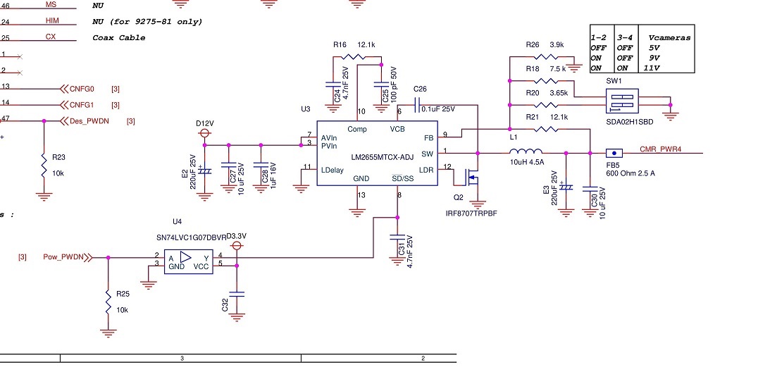
I am using LM2655MTCX-ADJ to make 5V from 12V.
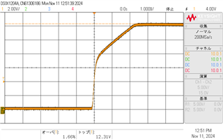
I drive the SD/SS terminal with SN74LVC1G07DBVR to delay the startup, but the current situation where the LM2655MTCX-ADJ breaks when shutting down is happening.

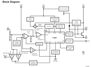
The data sheet of LM2655MTCX-ADJ says as follows.
[Do not drive this pin with an external source or erroneous operation may result.]
Is there any problem with shutting down using the SD/SS pin after startup?

  • Hi,

    Thanks for reaching out via e2e. The device should always be operated according to the indications given in the datasheet. Therefore, we recommend using the device with the SD/SS pin connected to ground through a capacitor.

    Kind regards,

    Federico

  • Thanks for the reply.

    I didn't have enough information, the capacitor and the output of SN74LVC1G07DBVR are connected in parallel on SD/SSpin.

    This allows the capacitor to charge and start running when SN74LVC1G07DBVR is turned off and shut down when SN74LVC1G07DBVR is turned on.

    The problem is that the LM2655 will break if the shutdown operation is performed after the capacitors are charged and started.

  • Hi,

    Can you share the schematic? I guess that situation is same as driving the SD/SS pin.

    Kind regards,

    Federico

  • Thanks for your support.
    The schematic is this: U3 of this circuit breaks when SD/SS is controlled.
    Is there anything wrong with it?

  • Hi,

    Thanks for sharing the schematic. According to what I see, the SD/SS pin is not being used properly. As mentioned in the datasheet, the SD/SS pin can be pulled low but it must not be externally driven (in this case with the Pow_PWDN signal through the SN74 part). Hence the wrong operation of the device.

    Kind regards,

    Federico

  • Thanks for the reply.

    U4 is an open drain output, would that still not work?
    I would like to know more about how the SD/SS pin can behave abnormally when driven externally.
    Can you tell me?
    Sorry for asking so many questions.

  • Hi,

    We're always happy to help and answer as many questions as we can, if possible. Unfortunately though, we can't share how the device behaves internally, as you will understand. All I can say about it is that the SD/SS pin should be connected to ground through a capacitor. However, you can always refer to the high-level block diagram mentioned in the device datasheet.

    Let me know if there's anything else I can do for you.

    Kind regards,

    Federico

  • Hello.
    I then tried to remove the U4 device and run it, but it still breaks U3 (LM2655).
    Why is this? Can you please point out if there is anything wrong with the circuitry?

  • Hi,

    I can't see anything wrong with the schematic, apart from the absence of LDELAY cap and the Schottky diode before the inductor (not mandatory, yet recommended). Is there a reason why you didn't use those?

    Also, just for my understanding, by "breaks" you mean that device is no longer good to go, right?

    Kind regards,

    Federico

  • Thanks for your support!

    The reason we have not added LDELAY caps and Schottky diodes is due to cost and placement location.
    I also installed and ran them with modifications and they broke the same way.

    By broken, I literally mean that U3 is broken and generates heat, and when I measure the resistance, there is a short to a few ohms between Pin1.SW and GND (I removed all components such as Q2 to check this).
    Also, this circuit was working before, and we are having trouble with a LOT of failures this time around.
    Is it possible that the LM2655 has been revised and the VIN MAX has been lowered so that it breaks when 12V is applied?

  • Hi,

    This is a very old device, still from National Semiconductor, so let's say that it's highly unlikely it has been revised.

    As you say that it was working before, can you summarize the conditions at which it was working and when it suddenly stopped working? This would help me understand what could happen, thanks.

    Kind regards,

    Federico

  • Thank you for your support.

    I will rule out SD/SS as it eventually broke after removing the U4.
    On a board that was working fine, power start was fine and output voltage changed depending on SW1 setting.

    On the defective board, the output voltage is very unstable: after giving D12V (AC adapter output), the protection circuit of AC adapter works when U3 is broken.
    The timing of U3 breakdown varies; some breakdowns occur immediately after power-on, while others occur suddenly after output voltage has been present for a while.
    However, the most common phenomenon is that it breaks immediately after power-on.
    The circuit components have not been changed from the normal board.

  • Hi,

    Is there a way for you to check whether the output voltage doesn’t rise above 80% of the normal value before the soft-start reaches 2V? Because in that case undervoltage protection will shut down the device. You can avoid this by either increasing the value of the soft-start capacitor, or using a LDELAY capacitor.

    Also, did you detect the first defect after a while (like n boards were working fine, n+1 breaks) or it was random?

    Kind regards,

    Federico

  • The current D+12V is slow rising and takes about 2mS to reach 12V. (Waveform attached)
    Accordingly, I changed the SD/SS capacitor from 4700pF to 0.01uF and tried to start up, but U3 is still broken in the same way. (It is not a protection as it generates heat due to lower resistance).

    The breakdown seems to be random.
    Is there any problem with running it without LDELAY and with SD/SS only?

    Thanks for your response, it is really helpful.