This thread has been locked.

If you have a related question, please click the "Ask a related question" button in the top right corner. The newly created question will be automatically linked to this question.

BQ25820: Unable to charge battery and REGN always 0V.

Part Number: BQ25820

Tool/software:

Hi,

I have designed using BQ25820RRVR with the following parameters:

  1. Vin: 6V to 50V
  2. Vout: battery only
  3. Battery: 3.6V LiFePo4 battery
  4. Charge rate: 1.5A max
  5. Discharge rate: 8A max
  6. Switching frequency: 250KHz
  7. Disable EN_PRECHG

I am currently able to read and write to the I2C register and observe that both ACFET and BATFET toggle ON/OFF, which is also reflected in the I2C register. For reference, I have removed the BATFET, and my battery is directly connected to VSYS. Additionally, based on the I2C readout, the device is not in Hi-Z mode.

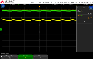
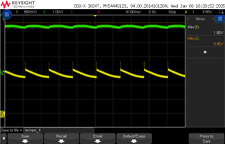
With a 12V input applied, I can see that the nPG pin goes LOW, while STAT1 and STAT2 remain HIGH. Despite these conditions, I am unable to enable charging, and the REGN voltage remains at 0.

Could you advise on what I might have overlooked to get the chip to function correctly? Thank you.

  • For context, after cross-referencing with the EVK schematic, the main difference is that we opted to remove the power path option by disconnecting VSYS from the AC input path. Instead, VSYS is now permanently connected to the battery.

    I might have missed it, but I didn’t see any special notes regarding VSYS apart from the SYS_OVP check in the buck controller, which led me to believe that connecting it directly to the battery would be a reasonable solution.

    My question is: Do you think disconnecting VSYS from ACIN could prevent the battery charging and buck controller from functioning correctly?

  • Hello Kenneth,

    My question is: Do you think disconnecting VSYS from ACIN could prevent the battery charging and buck controller from functioning correctly?

    Yes, If you are not using the direct power path function Pin 33 should be tied to PIN 32. If you make this change it should resolve the issue. If this does not resolve, will you provide your schematic?

    We are currently working to develope a schematic checklist for non-power path option for BQ25820, to prevent further confusion.

    Best Regards,

    Christian

  • Hi Christian,

    Thank you for your reply. I have connect VSYS to ACIN and the charger appears to be working (both STAT1/2 pin are now LOW when 12Vin applied) but it is still not charging. 

    In the plot above, the yellow line represents the battery path, while the green line corresponds to my raw battery input before the battery protector. I can see that the charger cycles up to 4.2V.

    However, the issue arises when a fault is detected—at 4.2V, it appears to trigger a battery overvoltage protection (OVP) event, which is reflected in my fault register (0x24).

    Below, I have attached a plot where the yellow line represents the signal probed at the FB pin, while the green line remains my raw battery input.

    I have also shared a snapshot of my register readout in the following format: Reg[Address]:[Data]

    00> Reg[0x21]: 0x 8
    00> Reg[0x22]: 0x80
    00> Reg[0x23]: 0x 2
    00> Reg[0x24]: 0x10
    00> Reg[0x25]: 0x 1
    00> Reg[0x26]: 0x 0
    00> Reg[0x27]: 0x10
    00> Reg[0x28]: 0x 0
    00> Reg[0x29]: 0x 0
    00> Reg[0x2A]: 0x 0

    I have attached my schematic for your review too. The only differnce here is that I have removed R16 and populated R15.

  • Hi Christian,

    I did more troubeshooting and found that the charger was able to charge under the following settings:

    1. Set VBAT_LOWV to 0x01 = 55% of VFB_REG
    2. Set REGHG to 0x00 = 93% of VFB_REG
    3. And bypass the battery protector IC: BQ298006RUGT

    Here is a plot I captured during the charging phase—green represents the battery voltage, while blue shows the battery current. Meanwhile, my register at 0x21 fluctuates between 0x0C (CV mode) and 0x0F (Termination Done). Does this behavior seem correct to you?

    And I have two follow up questions:

    1. Can this charger works with BQ298006RUGT?
    2. And using the BQ298006RUGT, if my battery is in shutdown mode, can this charger wakes it up? 

    Thank you for your help.

  • Hello Kenneth,

    Meanwhile, my register at 0x21 fluctuates between 0x0C (CV mode) and 0x0F (Termination Done). Does this behavior seem correct to you?

    Is the battery connected in this case?

    Do you have a system load?

    Can you provide a register dump?

    • Can this charger works with BQ298006RUGT?
    • And using the BQ298006RUGT, if my battery is in shutdown mode, can this charger wakes it up? 

    I do not support the BQ298006RUGT, I recommend posting a new question related to this device.

    Best Regards,

    Christian.

  • Hi Christian,

    I truly appreciate your quick responses.

    The battery is connected and there is no system load. Please see the register dump with nPG, STAT1 and STAT2 pin status together with my probe measurements. (Yellow = FB pin, Green = battery voltage, Blue = current measurement at battery). 

    The STAT1 and STAT2 pins are internally pulled up. If 0 = ON, 1 = OFF.

    Questions

    1. From the result, it appears to charge my battery and prematurely entires fully charge state. Did I messed up the resistors value or my register?
      1. I haved managed to notice a CC mode once that's only when my battery is at arounbd 2.1V - 2.4V.  
    2. From the oscilloscope snapshots below, I am also rather concerned that BQ25820 could cycle up to 4.2V when it reached the full charge mode. Is this correct too? 
    3. Noted on the BQ298006RUGT support. But could I check if my battery is 0V (at shutdown mode), could BQ25820 apply voltage to the battery nonetheless? I just need an external voltage applied to wake up the battery protector.

    Before charging

    00> Reg[0x00]: 0x10

    00> Reg[0x02]: 0x640

    00> Reg[0x06]: 0x640

    00> Reg[0x08]: 0x348

    00> Reg[0x0A]: 0x640

    00> Reg[0x0C]: 0x3E8

    00> Reg[0x10]: 0x140

    00> Reg[0x12]: 0xA0

    00> Reg[0x14]: 0x0F

    00> Reg[0x15]: 0x1D

    00> Reg[0x16]: 0x00

    00> Reg[0x17]: 0xC9

    00> Reg[0x18]: 0xC0

    00> Reg[0x19]: 0x24

    00> Reg[0x1A]: 0x20

    00> Reg[0x1B]: 0x96

    00> Reg[0x1C]: 0x57

    00> Reg[0x1D]: 0x40

    00> Reg[0x1E]: 0x00

    00> Reg[0x1F]: 0x00

    00> Reg[0x21]: 0x08

    00> Reg[0x22]: 0x00

    00> Reg[0x23]: 0x01

    00> Reg[0x24]: 0x00

    00> Reg[0x25]: 0x00

    00> Reg[0x26]: 0x00

    00> Reg[0x27]: 0x00

    00> Reg[0x28]: 0x00

    00> Reg[0x29]: 0x00

    00> Reg[0x2A]: 0x00

    00> Reg[0x2B]: 0x60

    00> Reg[0x2C]: 0x02

    00> Reg[0x2D]: 0x00

    00> Reg[0x2F]: 0x00

    00> Reg[0x31]: 0x00

    00> Reg[0x33]: 0x00

    00> Reg[0x35]: 0x00

    00> Reg[0x37]: 0x00

    00> Reg[0x39]: 0x00

    00> Reg[0x3B]: 0x00

    00> Reg[0x3C]: 0x00

    00> Reg[0x3D]: 0x1A

    00> Reg[0x62]: 0x02

    00> nPG = 1, STAT1 = 1, STAT2 = 1

    From here, you can see the battery is not at full capacity at around 2.8V.

    During charging

    00> Reg[0x00]: 0x10

    00> Reg[0x02]: 0x640

    00> Reg[0x06]: 0x640

    00> Reg[0x08]: 0x348

    00> Reg[0x0A]: 0x640

    00> Reg[0x0C]: 0x3E8

    00> Reg[0x10]: 0x140

    00> Reg[0x12]: 0xA0

    00> Reg[0x14]: 0x0F

    00> Reg[0x15]: 0x1D

    00> Reg[0x16]: 0x00

    00> Reg[0x17]: 0xC9

    00> Reg[0x18]: 0xC0

    00> Reg[0x19]: 0x24

    00> Reg[0x1A]: 0x20

    00> Reg[0x1B]: 0x96

    00> Reg[0x1C]: 0x57

    00> Reg[0x1D]: 0x40

    00> Reg[0x1E]: 0x00

    00> Reg[0x1F]: 0x00

    00> Reg[0x21]: 0x0C

    00> Reg[0x22]: 0x80

    00> Reg[0x23]: 0x02

    00> Reg[0x24]: 0x00

    00> Reg[0x25]: 0x01

    00> Reg[0x26]: 0x00

    00> Reg[0x27]: 0x00

    00> Reg[0x28]: 0x00

    00> Reg[0x29]: 0x00

    00> Reg[0x2A]: 0x00

    00> Reg[0x2B]: 0x60

    00> Reg[0x2C]: 0x02

    00> Reg[0x2D]: 0x00

    00> Reg[0x2F]: 0x00

    00> Reg[0x31]: 0x00

    00> Reg[0x33]: 0x00

    00> Reg[0x35]: 0x00

    00> Reg[0x37]: 0x00

    00> Reg[0x39]: 0x00

    00> Reg[0x3B]: 0x00

    00> Reg[0x3C]: 0x00

    00> Reg[0x3D]: 0x1A

    00> Reg[0x62]: 0x02

    00> nPG = 0, STAT1 = 0, STAT2 = 1

    Charge completed but my battery is still not at full capacity.

    00> Reg[0x00]: 0x10

    00> Reg[0x02]: 0x640

    00> Reg[0x06]: 0x640

    00> Reg[0x08]: 0x348

    00> Reg[0x0A]: 0x640

    00> Reg[0x0C]: 0x3E8

    00> Reg[0x10]: 0x140

    00> Reg[0x12]: 0xA0

    00> Reg[0x14]: 0x0F

    00> Reg[0x15]: 0x1D

    00> Reg[0x16]: 0x00

    00> Reg[0x17]: 0xC9

    00> Reg[0x18]: 0xC0

    00> Reg[0x19]: 0x24

    00> Reg[0x1A]: 0x20

    00> Reg[0x1B]: 0x96

    00> Reg[0x1C]: 0x57

    00> Reg[0x1D]: 0x40

    00> Reg[0x1E]: 0x00

    00> Reg[0x1F]: 0x00

    00> Reg[0x21]: 0x0F

    00> Reg[0x22]: 0x80

    00> Reg[0x23]: 0x02

    00> Reg[0x24]: 0x00

    00> Reg[0x25]: 0x01

    00> Reg[0x26]: 0x00

    00> Reg[0x27]: 0x00

    00> Reg[0x28]: 0x00

    00> Reg[0x29]: 0x00

    00> Reg[0x2A]: 0x00

    00> Reg[0x2B]: 0x60

    00> Reg[0x2C]: 0x02

    00> Reg[0x2D]: 0x00

    00> Reg[0x2F]: 0x00

    00> Reg[0x31]: 0x00

    00> Reg[0x33]: 0x00

    00> Reg[0x35]: 0x00

    00> Reg[0x37]: 0x00

    00> Reg[0x39]: 0x00

    00> Reg[0x3B]: 0x00

    00> Reg[0x3C]: 0x00

    00> Reg[0x3D]: 0x1A

    00> Reg[0x62]: 0x02

    00> nPG = 0, STAT1 = 1, STAT2 = 0

    The follow plot is a zoomed in view.

  • Hello Kenneth,

    From the result, it appears to charge my battery and prematurely entires fully charge state. Did I messed up the resistors value or my register?
    1. I haved managed to notice a CC mode once that's only when my battery is at arounbd 2.1V - 2.4V.  

    What is the charge voltage that you are trying to program? Based on the resistor setting the charge voltage is 3.6V is this correct?

    Noted on the BQ298006RUGT support. But could I check if my battery is 0V (at shutdown mode), could BQ25820 apply voltage to the battery nonetheless? I just need an external voltage applied to wake up the battery protector.

    Yes, the BQ25820 should be able to apply a voltage when battery is 0V

    Best Regards,

    Christian.

  • Hi Christian,

    It turns out that the SYS pin was the actual fix needed for the board. The other issue preventing the battery from charging was due to the PMOS reverse protection. The clamping diode was sized incorrect because it did not allow the PMOS to turn on when the battery voltage is 0V (Shutdown mode). Currently, I'm able to see the battery being charged in CC mode. I will do more testing and raise another question if new problem occured. 

    Thank you.

  • Hello Kenneth,

    That is good to hear, i will close this thread for now.

    Best Regards,

    Christian.