This thread has been locked.

If you have a related question, please click the "Ask a related question" button in the top right corner. The newly created question will be automatically linked to this question.

TPS552872: IC works ON for sometime and then doesn't turn ON

Part Number: TPS552872

Tool/software:

AFter Soldering back the IC, The output voltage is regulated. once you turn off the IC doesn't restart. ( Internal VCC pin 18 < 1 ). 

Load is not connected. I replaced the IC, it started working first time and drawing current of roughly about 50mA ( as seen in DC Supply ), I turned ONN and OFF a couple of times, it was working. I turned ONN after a while then the Current was increased to 120mA. I turned OFF and turned ONN again , Output voltage is 0. 

I have two boards, Each board, the same thing happens. It came for the first time, It doesn't turn ONN again. Please advise

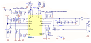
Note: i have used this iC in my previous version of board, similar schematic as shown below, never seen this type of behavior. 

  • Hi Mohammed,

    Thank you for reaching out. What is the input voltage and output voltage? Can you help provide waveforms of SW1, SW2, VOUT, inductor current if you still have more chips to replace? Can you provide layout file for me to check?

    Regards,

    Mulin

  • Hello mulin,

    I understand there's issue with my layout as I have not given proper thermal vias. Did some minor adjustments and now it's working.

    1.removed ferrite bead in between AGND and PGND. The Agnd and Pgnd shorting near to terminal of VCc capacitor is critical. I want to understand why. Without doing this change IC was not able to turn ONN and IC's were getting damaged. 

    2. Additionally the ic was heating severely, I removed both the RC snubber across inductor and heating has reduced drastically and also the bias current. I want to understand the use of RC SNUBBER and can we proceed without it ?

  • Hi Mohammed,

    Thanks for feedback, Mulin is OoO this week, please expect a delay for the response.

    BRs,

    Bryce 

  • Team, are we getting a response on this thread ??

  • Hi Mohammed,

    Sorry for late response. Below is my feedback.

    1. Ferrite bead introduces large parasitic inductance to the circuit. This parasitic inductance will cause large Ldi/dt spike in logic GND and cause internal logic mistake. In high frequency DCDC, we don't recommend to use ferrite bead between AGND and PGND. Just short or NET tie is ok.

    2.There is power loss in the RC snubber and thus there is thermal dissipation. You can reduce the capacitance to 330pF. We recommend to reserve RC snubber position to reduce SW spike and improve EMI performance. You can let the snubber NC first.

    3.Since you are using 2M switching frequency, it is possible that thermal performance is bad. Can you provide your working condition so that I check if the switching frequency is reasonable?

    Regards,

    Mulin

  • Vin : 9 to 32

    Vout : 15.8

    Iout : approx 150mA - 160mA 

    Load is connected to gate drivers other low voltage power converters and analog PWM controllers

  • Hi Mohammed,

    2M is suitable for this case. If you have concern about the thermal performance, please send me layout file.

    Regards,

    Mulin

  • 1. Ferrite bead introduces large parasitic inductance to the circuit. This parasitic inductance will cause large Ldi/dt spike in logic GND and cause internal logic mistake. In high frequency DCDC, we don't recommend to use ferrite bead between AGND and PGND. Just short or NET tie is ok.

    2.There is power loss in the RC snubber and thus there is thermal dissipation. You can reduce the capacitance to 330pF. We recommend to reserve RC snubber position to reduce SW spike and improve EMI performance. You can let the snubber NC first.

    Hello Mulin. Please elaborate on points 1 and 2 in more detail. I want to understand the issue. Appreciate your efforts and assistance.

  • Hi Mohammed,

    I will reply to you later today. Thanks.

  • Hi Mohammed,

    1.There will be current flowing GND plane. If you add large FB there, voltage spike in GND caused by Ldi/dt will be large, causing some logic mistake because GND has noise.

    2.Power loss in RC snuBber is CU^2. So if you reduce the capacitance, power loss will reduce and thermal dissipation will reduce also.

    Regards,

    Mulin