


Tool/software:
Good afternoon,
I use LM5149 to design a 24V to 12V, 5V, 3.3V 10A circuit, 4mΩ detection resistance, it is ok at normal temperature, now in the -40 degree environment start, can only reach 5A, trigger protection, and there will be howling, my parameters are obtained according to quick-start. Could you please tell me which parameters need to be paid more attention to when starting at -40 degrees, and the direction of change
THANKS


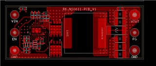
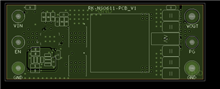
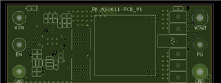
 all 2oz copper
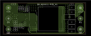
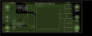