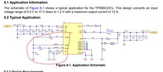
This thread has been locked.

If you have a related question, please click the "Ask a related question" button in the top right corner. The newly created question will be automatically linked to this question.

TPS56C231: PowerGood active before Output Ok

Part Number: TPS56C231

Tool/software:

Hi,

I use the TPS56C231 as 0V85 driver on a PCB with other Voltage supplies. I have following Power Sequencing: ... ->5V_REG -> 0V85 -> 0V9 -> ...

The 0V9 supply is activated with the PG signal of the TPS56C231 (PG_0V85)

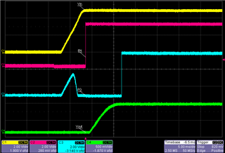
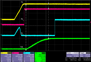
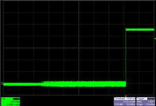
Measurements show that there is a short pulse of PG_0V85 before 0V85 is on:

This causes to enable 0V9 for a short time which is problematic.

PG_0V85 is pulled high with 10k to 5VREG:

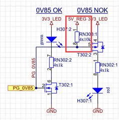
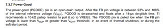
Other to this Pullup and the connection to 0V9 Driver Input, PG0V85 is not connected anywhere else.

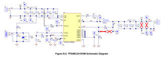
I could reproduce this behavior with the Eval-Board TPS56C231EVM.

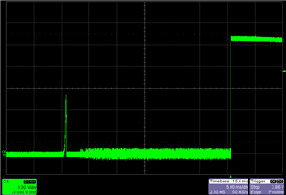
There I connected PG via 10k to Vin.

This shows a small Pulse on PG which should not be.

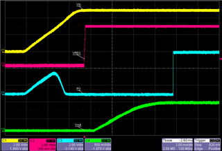
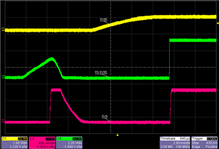
With the original circuit in which PG is pulled high to internal TPS56C231EVM voltage VREG5, this pulse does not occur:

My resumée:

  • Power Good output pulled to Voltage which is on before TPS56C231 enabled -> faulty short pulse on PG signal
  • Power Good output pulled to internal TPS56C231  VREG5 -> expected behavior without pulse

Is this a known issue? Or am I the only one who can observe this pulse? Is PG output undefined for some time during startup? Is it mandatory to connect PG to VREG5?

Thank you a lot

  • Hello,

    It looks like there is some glitch that is causing PGOOD to be asserted for a short time initially. This glitch can also be caused by EN signal, Vin signal, etc. How are these signals being supplied? can you provide more waveforms for VIN, Vout, EN, PG and VREG all together to see how this glitch can be caused? TI recommends a 10kohm pullup resistor pulled up to VREG5. Can you also try decreasing the slew rate of the power-up sequence? Slowing down the startup can smooth the signal and decrease risks for glitches.

    Thank you,

    Calan

  • Hi Calan,

    Thank you for your reply.

    The signals are supplied as followed:

    • Vin: LM73606RNPT voltage output (5V)
    • EN: Power Good output of LM73606RNPT, pulled up to Vin via 10k

    I measured the signals which you can see below:

    Vin, EN, PG, Vout:

    Vin, VREG, PG, Vout:

    I don't see any unexpected details other than the glitch on PG. Also the ramp up time of Vout is within expectation. Do you see any anomalies?

    In addition I found out that the PG glitch does not occur if the voltage supply is turned off and on again rather quickly (within 10sec). It does only occur when the device was powered off longer than around 30sec. This can be observed on my device and also on the evaluation board.

    In a next step I will increase the softstart time.

    Kind regards,

  • Update: Doubling the soft start time from 4.7ms to 9.4ms (additional 47nF) did not change the glitch:

  • Hello,

    Thanks for sharing these waveforms. Can you share your full conditions such as Vin, Vout, FSW, Iout? Also, is this being tested under any extreme ambient temperatures?

    Can you share your full schematic? The schematic of the evaluation board is fine since you mentioned this occurs on the EVM as well.

    Thank you!

    Calan

  • Hi Calan,

    See the schematic of my modified eval board (modified components listed below):

    • R3 is connected to Vin instead to VREG5
    • C7 = 200nF
    • R4 = 160kOhm
    • R5 = 20kOhm
    • Cout (C11..C16) = 200uF
    • Vin = 5V
    • Vout = 0.85V
    • FSW = 800kHz
    • Iout = 0A (open loop)
    • Tss = 21ms

    On the EVM I did not apply any load and the glitch occurred.

    I did all my tests at room temperature (20..25°C).

    With this modifications I can produce the PG glitch as following (same plot as in initial post):

    Can you reproduce the glitch on your side?

    (My design differs only in C7 [for which I have 47nF] and the load which is a Zinq Ultrascale+  FPGA XCZU4EV-1SFVC784E)

    For further details or clarifications I'm happy to help.

    Thank you a lot.

  • Hello,

    Thank you for providing this information. Here is my feedback for this:

    • R3 is connected to Vin instead to VREG5 - Modify
    • C7 = 200nF -  Modify
    • R4 = 160kOhm - Good
    • R5 = 20kOhm - Good
    • Cout (C11..C16) = 200uF - Good, ensure stays above 100uF effective Cout
    • Vin = 5V - Good
    • Vout = 0.85V - Good
    • FSW = 800kHz - Good
    • Iout = 0A (open loop) - Good
    • Tss = 21ms - Soft start will need to be faster than this

    Overall, the main potential issue I see with this is connecting PGOOD to VIN. Typically, I have not seen this in TPS56C231 schematics. Normally, the best approach is to connect it to VREG5 with 10kohm resistor. I believe this is the only reason for the glitch in PGOOD. The components and BOM for the most part look ok and do not seem to be related to this. Please attach PGOOD to VREG with 10kohm and please adjust the SS cap to 0.047uF. The Vin, Vout, and FSW conditions look normal.

    Best,

    Calan

  • Hi Calan,

    Thank you for the solution of the problem. Pulling PGOOD to VREG5 solved the issue with the glitch.

  • Hello Hi,

    I am glad this resolved the issue. I will now close this thread.

    If there is anything else, please reply to this thread or open a new thread, I will be happy to help.

    Thank you,

    Calan