This thread has been locked.

If you have a related question, please click the "Ask a related question" button in the top right corner. The newly created question will be automatically linked to this question.

TPS63901: Current in sleep mode of custom PCB should be around 7uA stable, but current from Buck-Boost converter is fluctuating from 7uA to 20uA

Part Number: TPS63901
Other Parts Discussed in Thread: TPS62040, , MSP430FR2475

Tool/software:

Hi,

I have a problem with the buck-boost converter. when there is no load i don't have a stable current usage. 

When the PCB is in power down it should consume around 6uA a 7uA. However the current is constant fluctuating from 7uA to 20uA.

in a previous design with the same components as the new design, i use the buck converter TPS62040, with that converter i had a stable 7uA current usage.

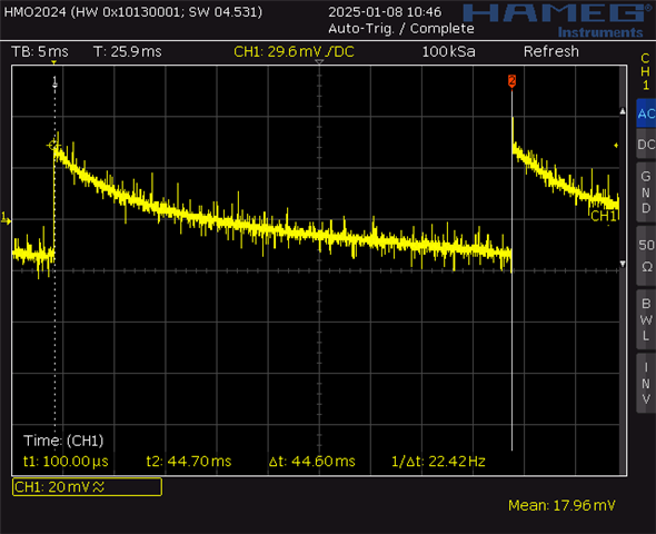
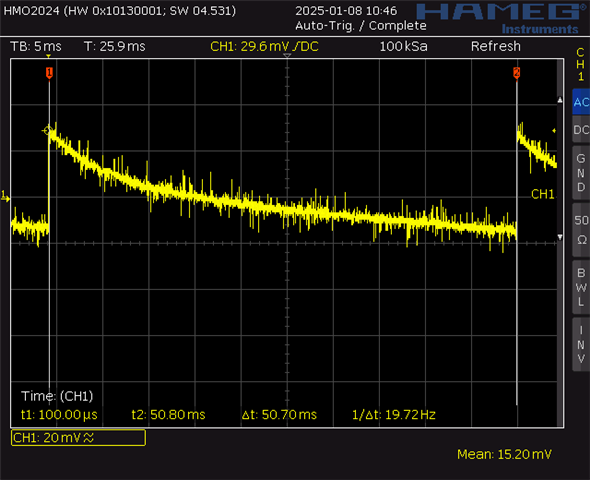
On the oscilloscope i see a fluctuating sawtooth in power down mode. it fluctuates from +-19hz to +-22 hz, the screenshots are in the attachments.

That fluctuating frequency corresponds with the fluctuating current in power down mode. When the PCB is not in power down mode, it consumes around 500uA.

In that case i see a stable sawtooth with stable frequency on the scope. 

I do have 3 other TPS63901 buck boost converters on the PCB which are turned off in power down by the uController.

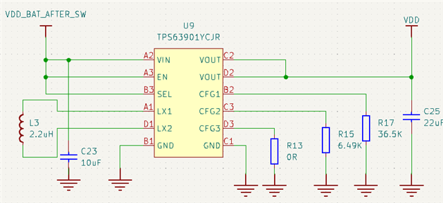
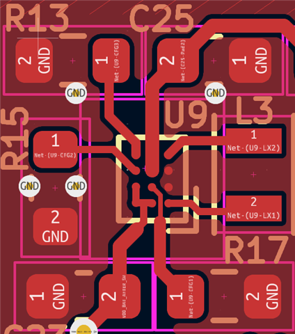
i also attached my design.

Can someone tell what causes this problem?

  • Hi  Marc,

    Shunt down mode in your description means all devices followed are disabled, right?

    How did you measure the input current? with a multimeter? What is the integration time of this multimeter?

    Kind reminder that current layout is not good enough, please take the layout example in DS as ref?

    Regards

    Tao

  • Hi Tao,

    Indeed, all devices disabled, 1 power supply(TPS63901) is active for the uController and some other low current Ic's. i tested also without any chips after the power supply, only the uController(MSP430FR2475) in LPM4 mode, but still the same fluctuating current.

    But what i said in a previous design with only a buck converter i had a stable current in LPM4 mode without other chips.

    I measure the input current with a multimeter(TENMA 72-8720) in serie, but i saw the variating frequency also on oscilloscope without multimeter in serie.

    I saw the layout example. i can route the coil traces on inner layer so i have a complete ground plane and move the input capacitor to the right.

    Is the current layout causing this variating frequency? because at a higher consumption the power demand is stable.

    I attached the datasheet file of the multimeter

    2616983.pdf

  • Hi Marc,

    One thing i am sure is that the IQ for this device is 75nA only.

    Assuming load is a constant micro amp in shunt down mode, device work in PFM, it makes sense that a sawtooth observed at output.

    I saw a Ture RMS mode in the DS if multimeter, could you try to measure again with this mode?

    Regards

    Tao

  • Hi Tao,

    The 75nA should be correct, but maybe the current layout causes it to go higher

    With all chips on the board and 1 power supply on, uController in LPM4 mode i measure this:

    In TrueRMS  i have an AC component steady 8.5uA  

    When i measure in TrueRMS AC + DC i measure steady 15uA 

    i expect steady 6uA a 7uA.

  • Hi  Marc,

    I not sure, but mostly, this high consumption should not caused by layout.

    Is it possible you can remove the MCU and redo this test again?

    Regards

    Tao

  • Okay i will do and let you know. i have 3 other power supplies(TPS63901) which i have to manual disable with the enable pin.

  • Thank you, from my experience, it should be caused by unexpected load. wait for your update here. 

  • I did the TrueRMS measurement one by one removing IC.

    it turns out that the AC component came from The battery management IC. I attach a screenshot of that part. The BMS chip consumes in power down 1uA. and powered from the BATT pin but somehow there is a AC component coming from it.

    without MCU, BMS and other components en 3 other power supplies disabled i measure approximately 50 nA to 100nA. that current is 99% of the time stable

    but at some point the current increase to 10uA maybe this is some external noise because i also have a 2 antenna's for GPS and NBIOT. I could not measure that peak with TrueRMS because it's random.

  • Hi  Marc,

    Yeah, so in summary. this different with former version is just caused by test set-up and some unexpected difference from your system. So, if no more questions, i would like to close this thread, ok?

    Regards

    Tao

  • Hi Tao,

    The only difference with previous version are the Power supplies. 

    In previous version i used Buck converter and this version Buck-Boost converter.

    Do you have any idea why it causes that behaviour with the schematic what i attached?

    If not i would close the thread and discuss it with the BMS manufacturer

  • Hi  Marc,

    No issue found about your schematic from my side. it shoule not be caused by TPS63901, I am sorry that no idea from my side.

    Regards

    Tao

  • Hi Tao,

    Thanks for your time and advice.

    Regards,

    Marc