Tool/software:
Hello,
Following some problems concerning the LM3409HV IC, I am here to provide you with my tests in the hope that you can help me resolve my problems.
I have to drive a string of 12 white LEDs in series that I have to be able to vary between 1A and 2A for my tests (Vf led @1A ~35V / Vf led @2A ~38V) with an input voltage of 48V. Below is my diagram with the values calculated according to the datasheet (9.2.1 EN PIN PWM Dimming Application for 10 LEDs) :
Vinput = 48V / Vout_led = 38V / Iled = 2A --> Rsense = 0.11ohms (0.22 // 0.22) / Fsw = 550kHz / Inductor value = 27µH

Once the whole system is connected, I send a 40kHz PWM with different duty cycles which correctly varies the intensity of the LEDs at the output, so far no problem.
On the other hand, in the case where I setup a PWM at a fixed duty cycle for example and I modify Vinput I observe a variation in the current of the LEDs. Moreover, depending on the % of duty cycle I did not have the impression that it was linear.
The datasheet specifies that the component operates in "Constant current source" and in figure 13 the PWM curve in function of the current seems linear.
So I preferred to buy the LM3409HVEVAL devboard in case I had made a mistake and test with the basic parameters :
Vinput = 48V (75V max) / Vout_led = 42V / Iled = 1.5A --> Rsense = 0.15ohms / Fsw = 400kHz / Inductor value = 33µH
To get as close as possible to the vout_led I modified my PCB to make strings of 14 LEDs in series. By putting the jumper on position 1 (pin 1 and 2 shorted) the driver lights up and regulates to 1.45A for a Vout at 44V with 48V input.
Still with my 14 LEDs in series, I then switch to PWM control mode on different duty cycles at a frequency of 20kHz :
PMW @ 10% : PMW @ 20% : PMW @ 50% :
- Vin 48V : iled = 79mA / vled 41.6V - Vin 48V : iled = 222mA / vled 41.6V - Vin 48V : iled = 662mA / vled 41.6V
- Vin 52V : iled = 109mA / vled 41.6V - Vin 52V : iled = 257mA / vled 41.6V - Vin 52V : iled = 690mA / vled 41.6V
- Vin 56V : iled = 124mA / vled 41.6V - Vin 56V : iled = 266mA / vled 41.6V - Vin 56V : iled = 707mA / vled 41.6V
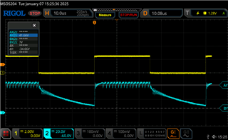
Below is an oscilloscope reading with the yellow curve is the PWM 50% at 20kHz and the blue curve is the Vled. The curves are almost identical on the other duty cycles.
I wanted to test with another version with 11 LEDs in series and still in the same parameters as previously without modifications to the LM3409HVEVAL devboard:
PMW @ 10% : PMW @ 20% : PMW @ 50% :
- Vin 44V : iled = 118mA / vled 33.6V - Vin 44V : iled = 262mA / vled 33.6V - Vin 44V : iled = 700mA / vled 33.6V
- Vin 48V : iled = 133mA / vled 33.6V - Vin 48V : iled = 278mA / vled 33.6V - Vin 48V : iled = 715mA / vled 33.6V
- Vin 52V : iled = 138mA / vled 33.6V - Vin 52V : iled = 283mA / vled 33.6V - Vin 52V : iled = 720mA / vled 33.6V
By modifying the Vin, we observe a slight variation of the current and on low currents we see the difference with the naked eye for example.
For the linearity of the PWM, depending on the output system we observe a shift, in theory with a PWM at 10% we obtain 145mA, with 20% we obtain 290mA and with 50% we obtain 725mA.
For my final system I have to operate at constant current to always provide the same light output (certification) while guaranteeing operation on 48V at +/-10%. In the current case the output current seems to be impacted by a variation in the input voltage which should not be the case with a LED driver.
Waiting for your suggestions, corrections or explanations, I wish you a good day.
Regard's, Maxime


 PWM 20%
 PWM 50%
 Vin = EN --> Should be like 100%
  PWM 20%
  PWM 50%
  Vin = EN --> Should be like 100%