This thread has been locked.

If you have a related question, please click the "Ask a related question" button in the top right corner. The newly created question will be automatically linked to this question.

TPS48111Q1EVM: Impossible to disable protections

Part Number: TPS48111Q1EVM

Tool/software:

Dear Support,

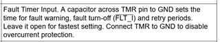
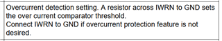
I'm having some difficulties to drive capacitive loads with high currents since protections kicks in. So I decided to try disabling both SCP and OCP on my EVM. To disable OCP I placed TMR with only the 100k to GND (R23) and IWRN connected to the 0ohm resistor (R26).

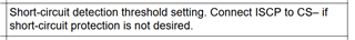
To disable ISCP I removed R14 and bypassed C8, in order to connect ISCP directly to CS- as stated in the datasheet.

The result is that some form of overcurrent still get triggered since FLT_I is driven low and the D4 turns on.

Can you please help me understand what is happening here?

Supply = 24V

Load = 4.7ohm

Thank you,

Kind Regards

  • Hi Riccardo, 

    Let me check on this. 

    Thanks,

    Sarah

  • Hi Riccardo, 

    At first glance it seems like you are doing things right. Can you provide more details on what load you are driving? Are you using the pre charge path? 

    I have seen this before and there are a few things to consider: 

    1.) Verify that your input Vin is stable. Its very possible that with driving high capacitive loads the input might dip down causing a UVLO event.

    2.) Please verify that with the load you are using the INRUSH controls are adequate and populated. The EVM out of box does not populate R15 and C9 for example. 

    You can utilize our TPS1211 calcualtor and FET SOA calculator to make sure you are accommodating expected loads. 

    https://www.ti.com/product/TPS1211-Q1#design-tools-simulation

    Thanks,

    Sarah

  • Dear Sarah,

    sorry for the late reply.

    1) I'll check the VIN, but I have increased the capacitor at the input in order to exclude that, but I'll check again. The UVLO will trigger an overcurrent fault?

    2) No, they are not populated, I'm only using the precharge resistor. The datasheet mentions also the possibility to do that by using only the precharge resistor, is that a viable solution? Can be preferrable than using resistor and capacitor on the main transistors?

    Thank you,

    Kind Regards

  • Hi Riccardo, 

    1.) No it looks like I confused this with a different device, but still a good idea to check the behavior of the Vin. 

    2.) Yes the pre charge resistor can be enough. It depends on your load. 

    Can you clarify the load you are using? Above you stated you used 24V and 4.7 ohms. This is only ~5A, which doesn't seem like very much. What is the capacitive load that you have? 

    Thanks,

    Sarah