Tool/software:
Hi,
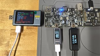
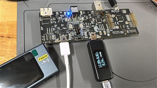
I am working on a power design which draw 25W from 15V PD channel (either Port A or B)
Meanwhile, I would like to charge the external device with PD 15V with 1A.
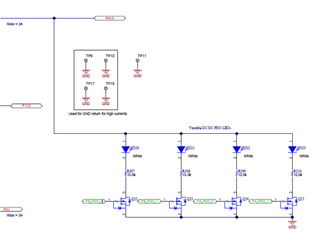
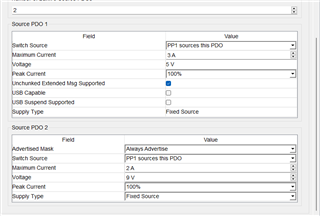
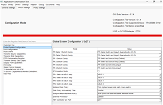
I try to set the project as attached,project5.pjt
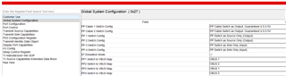
The result is I can change the transmit sink in either port by the setting (5/9/12/15/20 V) freely.
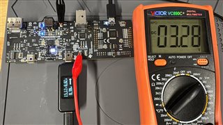
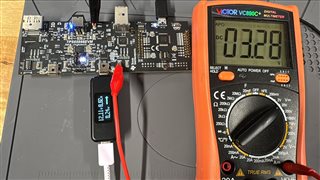
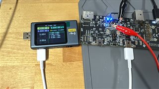
But the output is always keep only 5V, 0.9A not matter how I change any value.
When I plug in Port A, the Port B only output 5V 0.9A for iPad,
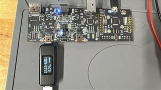
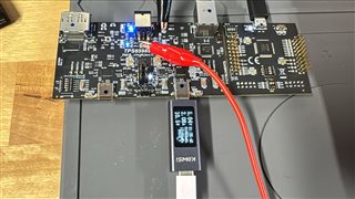
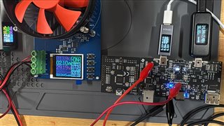
When I plug in Port A only, The LED, D3 is slightly dimmer than D5 (I know it indicate the voltage level, which means Port A has higher voltage then Port B)

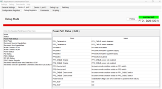
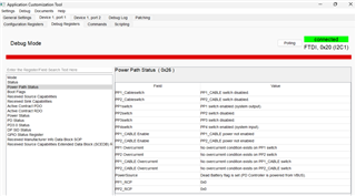
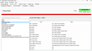
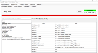
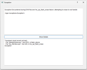
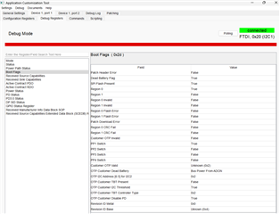
When I go into debug mode, the "Received Sink Capabilities" is always 0
Also, I try to keep all the setting as consistent as it could for 2 ports.
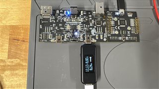
But I can't got Port A as output when I plugin the power source into Port B(act as a source).
When I plug in Port B, only LED D3 light up and D5 didn't turn on, no matter I plug in Port A or not.

I thought the PDO_1, and PDO_0 should be light up to indicate the PD voltage level?
And I guess all IMXCTL0, IMXCTL1, IMXCTL2 LED should light up in a proper way to show the power line between 2 ports?
Is that any potential that the board might have failure or is my configuration have some mistake.
Here is also my log3223.log2.csv.
Thanks for you helps!