This thread has been locked.

If you have a related question, please click the "Ask a related question" button in the top right corner. The newly created question will be automatically linked to this question.

TPS2116: Protection of inputs

Part Number: TPS2116
Other Parts Discussed in Thread: TVS0500

Tool/software:

Hello E2E forum,

We are using the TPS2116 to switch between two batteries (maximum 4.08V) to power our product.

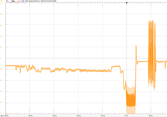
We have encountered that approximately 1% of our solutions fails due to the TPS2116 (output of the TPS2116 is crashing).

We suspect that this error is introduced by hot-plugging of batteries. The absolute maximum input voltage of the TPS2116 is 6V:


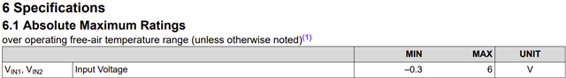
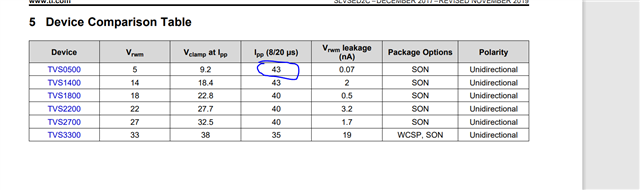
We are protecting the input to TPS2116 with a TVS diode. However, we're unable to find TVS diodes with a tight enough ratio between breakdown voltage and clamp voltage, since our operation voltage is maximum 4.08V. 
This suggests using TVS diodes with V_BR > 5V and V_CLAMP < 6V, which, as far as we're concerned, is not produced.

Hot-swap controllers in front of the TPS2116 is not possible since (as far as we're concerned), these devices consume quite alot of quiescent current. Our product consumes maximally 18 uA, so protection must not contribute significantly to this.

How would you recommend protecting the TPS2116 properly?

Best regards, Daniel

  • Hi Daniel,

    You can consider flat clamp TVS like this TVS0500 .  If hot-plug current is like 5-10A then it should clamp at lower level. You can also try playing with input cap.

    What is fail signature?

    Regards

    Kunal Goel

  • Hi Kunal,

    Never stumpled upon these flat clamp TVS types. They indeed look interesting!
    Hot-plug current is maximally measured to approx. 4A.

    By nominal specs alone (clamp voltage 9.5V, breakdown voltage 7.8V), I won't feel so confident in using this. Can you elaborate a bit on that they should "clamp at lower levels?"

    Already using the TVS diode TSD05DYFR, these seems to have some sort of the same (in fact, lower) characteristics.
    However, these are placed at the battery input rather than the TPS2116 input. I guess moving these (or TVS0500) as close as possible to TPS2116 inputs will improve protection? Or should I keep them at the source input (battery terminals)? From battery source to TPS2116 is approx. 10 cm long, 1mm wide track.

    In newer designs, I have designed for the use of a 22 uF X7R input caps with ~0.1 ohm series resistance attached in parallel to each battery at the battery connector aswell (or just tantalum).

    For this particular case, the voltage on the VOUT pin looks like this. This is observed in a quasiperiodic manner of approx. 800 ms:

    The source voltage (input 1) is stable (Li-Ion battery at 3.6V). Nothing is leaking to input 2. 
    Worth noticing is that if input 1 is disconnected and applying the same voltage source to input 2, the error disappears.

    Best regards, Daniel

  • Hi Daniel,

    Let me check and get back.

    Regards 

    Kunal Goel 

  • Hi Daniel,

    1. Placing close to VIN pin will be more effective.

    2.  at 43A it will clamp at 9.2V, so for 4A current it should clamp around 5.5-6V. 

  • Hi again,

    1. OK - will do that.
    2. How do you deduce this? Will the same apply for the TVS diode TSD05DYFR?

  • Checking on it asap. 

  • Hi Daniel,

    I do some rough calculation. Calculate Rdiode as (Vclamp at ipp - VRWM)/IPP.

    VClamp at IL= Vrwm + Rdiode*IL.

  • Hi Kunal,

    Thank you for this! I see that TVS0500 has active circuitry in it. So will these rough calculations also be applicable to ordinary TVS diodes (e.g. TSD05DFYR)?

    Reason for the question is that the TVS0500 has some significant footprint to it and it will be quite hard to incorporate this in the design.

  • These calculations should be applicable to ordinary TVS also, 

  • Hi again,

    Thank you! With all the suggested improvements to protection circuitry, this leaves me confident in (again) using the TPS2116 power mux in my design.