This thread has been locked.

If you have a related question, please click the "Ask a related question" button in the top right corner. The newly created question will be automatically linked to this question.

TPS25730: Some questions

Part Number: TPS25730
Other Parts Discussed in Thread: TPS25751

Tool/software:

Hi team,

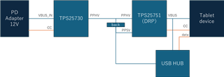
I am considering a configuration that combines the TPS25730D and TPS25751D. The TPS25730D is connected to a PD adapter, which charges the device at 12V through the PPHV of the TPS25751D.
When the PD adapter is disconnected, the device will supply power internally through VBUS.
In other words, I want the TPS25751D to act as a DRP.
So I have the following questions.

1.When the PD adapter is disconnected, the PPHV of the TPS25730 continues to receive power from the device.
Is there any concern about heat generation?

2. When the PD adapter is connected from state 1, is there a problem with the voltage batting?

Best Regards,
Ryu.

  • Hi Ryu,

    Would you mind making a rough block diagram showing your intent? This will help me get the clarity needed to answer your question.

    Regards,

    Conner

  • Hi Conner,

    Thanks for the reply.
    Do you get the image here?

    Best Regards,
    Ryu.

  • To clarify:

    1. PD Adapter 12V is a type C port that will only ever source power to the TPS25730. In this state, the TPS25751 would be a source to the Tablet device port.

    2. When no source is connected to PD Adapter 12V, the Tablet device would need to act as a source to power the system, via the TPS25751.

    Are the above two points correct?

    Regards,

    Conner

  • Hi Conner,

    Thanks for the reply.
    I hit the solved button by mistake.

    1. PD Adapter 12V is a type C port that will only ever source power to the TPS25730. In this state, the TPS25751 would be a source to the Tablet device port.

    Through the TPS25730, 12V is supplied to the PPHV of the TPS25751, which in turn supplies power to the Tablet.
    In other words, I want to power the tablet with 12V, not 5V.

    2. When no source is connected to PD Adapter 12V, the Tablet device would need to act as a source to power the system, via the TPS25751.

    That is correct.

    Best Regards,
    Ryu.

  • From what I understand of your application, you would only need the TPS25751. You would not need 2 USB-PD controllers for this application. The TPS25751 has the ability to negotiate the 12V.

    In regards to your original questions, I see no issue with heat generation at 12V, as these PD controllers are designed for all USB-PD SPR voltages and currents.

    If you choose to have PPHV rail of both the TPS25751 and the TPS25730 connected, and you have each port negotiating a different voltage, you can run into issues yes. But you would need a more detailed/clear architecture to determine what those issues/solutions would be.

    Regards,

    Conner

  • Hi Conner,

    My understanding is that each device is needed for CC negotiation with the PD adapter and CC negotiation with the tablet, but can this be achieved using one TPS25751?
    If so, what kind of circuit configuration should I use?

    If you choose to have PPHV rail of both the TPS25751 and the TPS25730 connected, and you have each port negotiating a different voltage, you can run into issues yes. But you would need a more detailed/clear architecture to determine what those issues/solutions would be.

    What can I offer?

    Best Regards,
    Ryu.

  • I am unclear as to the purpose and functionality of your design.

    You have two Type-C ports with their power paths connected directly in your diagram. If the TPS25730 is actively sinking 12V and the TPS25751 negotiates a source or sink contract that is not 12V, you would run into issues. Are you planning on using a Buck-Boost to connect the internal power rail, or are you planning on only allowing a 12V contract with the TPS25751? Or something else?

    Regards,

    Conner

  • Here is a state-by-state description of what I would like to do.
    1. when the USBPD adapter is connected
    Charge the tablet with 12V from the PD adapter.
    The TPS25751 is powered by the adapter.
    Also, the tablet and the device communicate with each other via the internal HUB.
    2. when the USB adapter is not connected
    Power is supplied from the tablet.
    The USBHUB is also powered by the tablet, and the devices communicate through the internal HUB in the same way as when the adapter is not connected.
    3. When the tablet is connected and the PD adapter is connected later
    Switch to power supply from the PD adapter.
    In other words, it will be in the state 1.

    I believe that two devices are needed because CC negotiation is required for each of these PD adapters and tablets.

    Best Regards,
    Ryu.

  • Hi, 

    TI U.S. is on Holiday today. Please expect some delay in responses. 

    Best Regards, 

    Aya Khedr 

  • Hi Ryu,

    Have you been working with Jeffrey Chung on this?

    Regards,

    Conner

  • Hi Conner,

    I do not know Mr. Jeffrey.

    Best Regards,
    Ryu.

  • My apologies. I am working with my peers on a suitable solution for your proposed system now that I fully understand it. I will try to get you the answer by tomorrow, but it could be as late a Monday.

    Regards,

    Conner

  • Hi Conner,

    Thank you for considering the solution.
    I look forward to your reply.

    Best Regards,
    Ryu.

  • Hi Ryu, 

    Conner is currently out of office. Please expect some delay in responses. Thank you in advance. 

    Best Regards, 

    Aya Khedr

  • Hi Ryu,

    I'm back in office and waiting on a peer to get back to me, hopefully today (tomorrow at the latest).

    Regards,

    Conner

  • After digging further. this type of implementation would constitute USB-PD passthrough, which we do not support at this time. One of the reasons for this is that the implementation would not be USB compliant.

    Kind regards,

    Conner

  • Hi Conner,

    I'm sorry, I don't quite understand what you're saying.
    How do I deal with this?

    Best Regards,
    Ryu.

  • This type of solution is commonly referred to as a USB Passthrough design, which we do not support for these devices at the moment.

    I would recommend looking into a system with an EC and a power mux.

    Regards,

    Conner