This thread has been locked.

If you have a related question, please click the "Ask a related question" button in the top right corner. The newly created question will be automatically linked to this question.

TPS65994AD: TPS65994BH: Re-timer FW failure with F909.12.30

Part Number: TPS65994AD
Other Parts Discussed in Thread: TPS65994BH

Tool/software:

Dear TI

For Intel re-time FW capsule update in BIOS, I encounter a FW update problem.

My environment: 

CPU: Intel Meteor Lake

OS: WIN11 24H2

Retimer FW: HBR_MTLARL_MPS_A0_6.23.1V3_Rel_ALL_Prod_PV1_External_SEC1_sign.bin

Attempt to update to: HBR_MTLARL_ALL_ALL_6.24.2V2_Rel_ALL_SEC1_PROD_external_sign.bin

1. With F909.12.06 base, I can do re-timer capsule update successfully (After install driver, WIN11 reboot, and BIOS can update the re-timer FW, progress bar in BIOS finished in 60s)

2. With F909.12.30 base, I can NOT do re-timer capsule update successfully (After install driver, WIN11 reboot, and BIOS can update the re-timer FW, progress bar in BIOS finished in 7s)

3. I narrow down the issue: the WIN11 device manager > Device Firmware > Firmware version

In F909.12.06 base, Device Firmware Version can show the firmware version as 26F (which is 623)

In F909.12.30 base, Device Firmware Version always show 0

4. Here is the step I force the BIOS to fetch the firmware version: In UEFI shell, delete the variable TbtRetimer1Version

5. Do I need to send the pjt file to you, if so, where to send ?

  • Hi,

    One of our team member will reply to this shortly.

    Regards

  • Hi Patrick! 

    UEFI capsule update is done by setting Retimer into a Retimer FW Update mode and is typically done via the I2C1 interface from the EC that will control the PD controller. The PD controller will then format the retimer via the I2C3 interface. 

    It sounds like the F909.12.30 is having issues flashing. I would like to ask what is driving the need to move from F909.12.06 to F090.12.30? 

    Thanks,

    Chris

  • Hi Chis

    1. Because if we are not using F909.12.30, we can not pass the PD citification (TEST.PD.USB4.EUSB.05 tEnterUSBWait check for USB4 DFP)

    2. But to let re-timer capsule update successfully, we have to use  F909.12.06 as base.

    3. some question that I am courious.

    UEFI capsule update is done by setting Retimer into a Retimer FW Update mode and is typically done via the I2C1 interface from the EC that will control the PD controller. The PD controller will then format the retimer via the I2C3 interface. 

    ----> Just curious, may I know by using which register of Hayden Bridge (0x04? 0x05? 0x07?), PD format retimer ?

    ----> As my guess, BIOS will use LSx signal to tell retimer to do some Flash stuff.( I refer from Hayden Bridge 1.28.pdf, retimer date sheet) 

    Thansk

  • Just curious, may I know by using which register of Hayden Bridge (0x04? 0x05? 0x07?), PD format retimer ?

    0x07. I will keep the discussion related to the TPS65994BH part to avoid NDA discussions. This is the process that I think is failing and would need your help in confirming. 

    • BIOS will set bit 15 in 0x52 register of the TPS65994BH. This enables the Retimer Compliance Support. This is done via I2C1 
    • Next, EC will either drive a GPIO or send the 4CC 'Trig' command. If your PJT has a GPIO assigned to 'Retimer_SoC_OVR_Force_PWR_Event (42) then I2C1 should not be sending the 4CC command.
      • GPIO option: System (EC or some other device) will drive the GPIO assigned to Retimer_SoC_OVR_Force_PWR_Event high. This will cause the Retimer signals to be enabled.
      • 4CC option: I2C1 will send the 4CC 'Trig' command with EdgeType = rising-edge (0x01) and GPIO Event = 'REtimer_SoC_Force_PWR_Event (0x2A)
    • When the GPIO/4CC drives this event high, the PD will send a write to 0x07 register of the retimer. Then read-back the 0x07 register.

    I suspect the issue you are seeing is the I2C3 write to 0x07 is NAKing from the retimer on startup. Here is what I need from you to help debug this further: 

    • Can you probe I2C1 + I2C3? Retimer enable signals (RESET_N, and LS_EN) would be good too but not NEEDED). Ideally these should be captured on a Ellisys or Saleae logic analyzer. 
    • Please share your PJT so I can try it out on my system

    Follow-up questions:

    • If we find a solution/fix that requires modifying the EC code will that be a solution for you? The modification may be timing-related or resending 4CC commands. 

    Thanks,

    Chris

  • Hi Chris

    Sorry for the late.

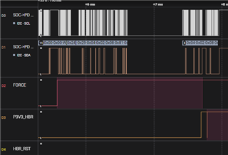
    Here is the fail capture from capsule update, you can see there are 0x07 command from PD->Re-timer.

    Here is also try this pjt I use(base on  F909.12.30). when you downloaded it, please delete it, or let me to know, then I can delete it.

    Btw, we use EC less, our BIOS do not set bit 15 in 0x52.

    but BIOS has set bit11 in 0x29, and check bit2 in 0x59.

    and let Retimer_SoC_OVR_Force_PWR_Event happened (by set GPP_B21 to HIGH).

    And it can do capsule update at successfully with F909.12.06.

    But  can not update successfully with F909.12.30

    TITANIUM_TPS65994BH_v2.1.0.pjt

     After_del_TbtRetimer1Version.zip

  • I have downloaded the files. 

    There is a timing issue happening that is causing this failure. 

    There is a change in the F909.12.30 where the PD will no longer retry writes to 0x07 5 times anymore. This is something that can be mitigated for now with the timing adjustments below:

    • The FORCE GPIO needs to be sent well in advance of the 0x29 bit 11 being written. (100+ms)
      • The P3V3_HBR looks to be the power rail of the retimer. Retimers take ~120ms to load FW from SPI after power on. It is expected that whenever Retimer FW Update process is started the retimers will be out of reset and have gone through the inital loading from SPI. 

      So recommended changes:

      • Make sure retimers have 120ms to load from SPI before asserting the FORCE GPIO
      • Do not set bit 11 in 0x29 until 100+ms after FORCE GPIO is sent
    • Hi Chris.

      Thanks for the analysis, I will have a try and let you know.^^ (Do not set bit 11 in 0x29 until 100+ms after FORCE GPIO is sent)

    • Thanks Patrick for the update! Please capture any Saleae logs if possible during testing and provide pass/fail update!