This thread has been locked.

If you have a related question, please click the "Ask a related question" button in the top right corner. The newly created question will be automatically linked to this question.

TPS26750EVM: EVM PD EPR (24V 5A) + USB2.0 Setup

Part Number: TPS26750EVM
Other Parts Discussed in Thread: BQ25756EVM,

Tool/software:

Hi,

I am trying to demonstrate a single USB-C cable solution for PD EPR (24V 5A) + USB2.0. Basically a setup of Source board-Sink board system for proof of concept. Would I be also to achieve this setup with 2x TPS26750EVM (1 source and 1 sink)? The EVM demonstrated in the User Guide was used in conjunction with BQ25756EVM (battery charge controller).

I would like to confirm if the EVM could work just by itself without BQ25756EVM (battery charge controller) to achieve PD EPR (24V 5A) + USB2.0, as our application is not related to charging. We are simply transferring 24V power from one board to another, while passing the USB2.0 D+/D- lines from source board to sink board at the same time.

Thanks!

Ming

  • Hi Ming,

    I would recommend using the BQ25756EVM, as it will be able to provide the voltages required (as it has a buck/boost converter) when the source first provides 5V for the implicit type-C contract, then 20V as it enters EPR mode, and then 24V at the final USB-PD contract.

    Regards,

    Conner

  • Hi Connor,

    Thanks for the reply. I still would like to try TPS26750EVM as a stand-alone device without BQ25756EVM.

    Could you please comment on what issues I may face if I try to set up the following scenario:

    Equipment:

    1. 1x TPS26750EVM configured as a source with 24V 5A capability. (I will call it sourceEVM)
    2. 1x TPS26750EVM configured as a sink with 24V 5A capability. (I will call it sinkEVM)
    3. 1x  240W EPR Lead, 1m.
    4. 1x Programmable bench power supply.

    Step:

    1. Set the output of the programmable bench power supply to 24V 5A.
    2. Connect the output of the programmable bench power supply to J8 of sourceEVM, short J1 and J7 of sourceEVM. 
    3. Switch on the programmable bench power supply, the sourceEVM should be initializing and once it's done. 24V should be observed at TP1 (VBUS).
    4. J15 is unpopulated on the sinkEVM to activate the Dead Battery Always Enable Sink Mode, which force U10 to be closed by default. All these are done when sinkEVM is unpowered ("Dead Battery"). 
    5. Connect one end of the USB-C cable to J4 of sourceEVM and the other to J4 of sinkEVM (which is completely unpowered, I think it is equivalent to what you called "Dead Battery" condition)
    6. Now, the PD controller of sinkEVM will be directly powered by whatever voltage that is on the VBUS from J4 through an internal high-voltage LDO, which in our case: converts the 24V VBUS to 3.3V.
    7. The sinkEVM's PD controller then loads the config and finishes initialization. Once these are finished for sinkEVM, it will see itself negotiating 24V from sourceEVM. However, nothing on the VBUS line would change after this PD contract process is finished because the VBUS is already at 24V.
    8. The whole process completed and the sourceEVM continuously supplies sinkEVM.


    Please let me know if I have mistaken anything above, as I am new to USB-C PD topics.


    Thanks,

    Ming

  • Hi Ming,

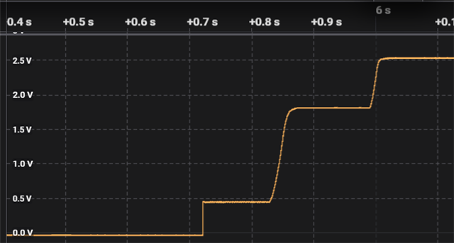
    Unfortunately, this violates USB-PD spec in a pretty egregious way. The below plot of VBUS shows behavior in a basic EPR negotiation. There should never be a "hot" voltage on VBUS when disconnected (for a Type-C cable), and when an implicit type-C contract is made, it is always at 5V. I've also attached a link to a document that goes over the basics of USB-PD EPR here.

    This plot is of VBUS, divided by 11. It shows a transition from 0V -> 5V -> 20V -> 28V. (as this shows a 28V capable source).

    Regards,

    Conner