This thread has been locked.

If you have a related question, please click the "Ask a related question" button in the top right corner. The newly created question will be automatically linked to this question.

LMZ23605: LMZ23605

Other Parts Discussed in Thread: LMZ23605

Tool/software:

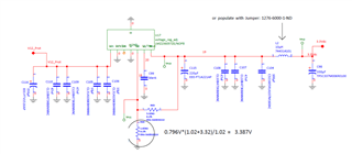
We are using the LMZ23605 with 12V in and set up for 3.3V out. Our application is for 3A max load on output.

We had a failure of this part in our application where the output (pin 7) appears to be shorted. There is no output voltage 

and the output measures 3.5 ohms with an ohmmeter. Since the part has output short circuit and thermal protection and we are not loading the output 

anywhere near the 5A maximum we are wondering how the part may have failed.

We are not using the part in a high temperature environment (35C max)

We are connecting the PGND/EP to AGND properly as specified in the datasheet.

Any information on how this may have occurred would be great. Are there any known issues with the part?

Any history of failure analysis would be helpful.

Thank you

  • Hi Frank,

    Thank you for that information. Please also share your schematic and layout and I would be happy to review these with you.

    Thank you,

    Joshua Austria

  • Hi Joshua,

    Thanks for the response.

    This is a classified project so I can't share much. The schematic is shown below:


    We removed the part from the board and found that the Exposed PAD/PGND was shorted to AGND (~0.8 ohms).

    I think these should be isolated and connected only on the circuit board.

    Also we are leaving the enable line open circuit (floating) as mentioned on page 18 of the datasheet as there is an internal pull-up to enable the regulator.

    The absolute maximum rating in the datasheet is 5.5V on the enable pin. We are measuring 6.4V with the enable pin floating. I this an issue?   

    Thanks,

    Frank 

  • Hi Frank,

    Enable should not be higher than 5.5 V as this goes above the abs max ratings as stated within the datasheet. In the case that Enable is left open, the internal UVLO is stated to occur at 4.3 V (please see section 8.2.2.2 of the datasheet).

    Were the exposed pad and AGND welded to each other or were they electrically shorted i.e. via a continuity test.

    Would it be possible to do an ABA swap with this IC and a fresh EVM? The purpose of this test is to determine if it is an IC issue or a schematic issue that may be causing the issue.

    Thank you,

    Joshua Austria

  • Hi Joshua,

    The exposed pad and AGND were measured with an ohmmeter and read ~ 0.8ohms (so electrically shorted).

    We ordered some actual parts and an EVM for the LMZ23605 so what you stated is a good next step (ABA swap).

    Thanks!

    Frank

  • Hi Frank,

    Sounds good. I will await the results of this test and we can continue our debug from there.

    Thank you,

    Joshua Austria

  • Hi Joshua,

    We replaced the LMZ23605 on the original board that had the failure, and the board is working fine now.

    So we are still wondering what happened to the part. 

    I also got the eval board for the chip and got that running. I did notice that on the Eval board with the enable pin floating

    the pin floats up to 6.4V just like our boards do. The max on this pin is 5.5V per the datasheet. Is this only for an externally driven enable?

    Thanks,

    Frank 

  • Hi Frank,

    Is this the voltage that you are seeing on the pin? Which board are you using (DEMO or EVAL)?

    Thank you,

    Joshua Austria

  • Hi Joshua,

    It is the voltage on the enable pin of the chip (pin 3). I am using the EVAL board.

    I removed Renh so the enable pin is unconnected to anything and floating similar to the 

    way we are using it.

    Thanks,

    Frank

  • Hi Frank,

    Understood. Thank you for confirming.

    Yes EN can be left floating for this device as it has an internal pull-up. Just a couple more questions:

    What is the input/output profile that this device was running in when the device failed (VIN, VOUT, IOUT, FSW)?

    Was L2 shorted or connected?

    Thank you,

    Joshua Austria

  • Hi Joshua,

    VIN= 12VDC, VOUT= 3.3VDC, IOUT = 3A max

    The sync is not used and this pin is grounded per the datasheet, so the free running FSW should be 812kHz

    Thanks,

    Frank

  • Hi Frank,

    Thanks for that. Please also confirm my previous question about L2. 

    Also please share your layout when you get the chance so I can review that as well.

    Thank you,

    Joshua Austria

  • Sorry forgot- L2 is not shorted. I'm not sure about sending the layout since it is classified. I'll find out.

    Thanks,

    Frank

  • Hi Frank,

    Sounds good. 

    Is this inductor a part of the input filter for a device downstream of the module? Can this be shared?

    The layout would be the next step in reviewing your issue. If there is a concern about the publicity of this forum, you can always send me a direct message on E2E.

    Thank you,

    Joshua Austria

  • Hi Frank,

    As it has been some time I will close this thread. Should you require further assistance, please respond with the requested information to re-open this thread.

    Thank you,

    Joshua Austria