This thread has been locked.

If you have a related question, please click the "Ask a related question" button in the top right corner. The newly created question will be automatically linked to this question.

BQ76907: Cell Protections Delay setting and Current protection threshold setting

Part Number: BQ76907

Tool/software:

Dear TI support team,

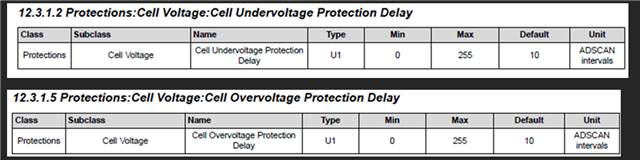
1.Do you have any documents, advice, or examples on how to calculate the cell under-voltage and over-voltage protection delay?"
2.How can I calculate the ADCSCAN interval for 3 seconds (5 cells)?"

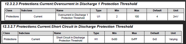
3.Do you have any documents, advice, or examples on how to calculate overcurrent in the discharge protection threshold and short circuit threshold? I’m using a 300 µΩ Rsense.

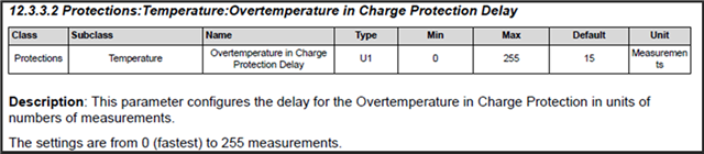
4.What does the measurement mean

Thank you for your assistance.

  • Hello Tom,

    1. I found this previous post that may help answer your question: BQ76907: COV and CUV Delay Time Setting.

    2. Section 5.1.1 Voltage Measurement Schedule in the BQ76907 Technical Reference Manual (TRM) helps further explain how the ADSCAN and measurement loop works.

    3. Section 6.7 Overcurrent in Discharge 1 and 2 Protections and Table 6-13. Overcurrent in Discharge Protection Operation in the TRM shows how the overcurrent in discharge protection works. The differential voltage detected at the SRN and SRP pins are compared to the protection threshold the user chooses and depending on the value, will trigger Safety Alert A() if configured to do so.

    The protection threshold as shown in the picture you shared, is 8mV by default. With a 300uOhm resistor, I = V/R, so your OCD is set to trigger around I = 8mV/300uOhm = ~26.67A.

    Section 8.2.1 Design Requirements and Section 8.2.2 Detailed Design Procedure in the BQ76907 Datasheet gives an example of a design with certain settings and how certain things such as the sense resistor are calculated and chosen to fit the design specified.

    Section 8.2.3 Application Performance Plot in the datasheet also shows the response to a short circuit in discharge (SCD) event with certain settings selected to show an example of what it would look like, for reference.

    4. The unit measurements refers to the settings for the voltage and current ADC measurement speeds. I will double-check this one with another colleague as well.

    Best Regards,
    Alexis