This thread has been locked.

If you have a related question, please click the "Ask a related question" button in the top right corner. The newly created question will be automatically linked to this question.

UCC25660EVM-064: UCC25660EVM-064 schematic error

Part Number: UCC25660EVM-064

Tool/software:

Hello.

I believe you did a mistake in the EVB.
In case of EVB connected to AC grid, you need an additional TP, and wire jumper, to deliver energy to the HB part.
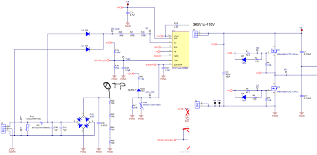


Alongside to that:


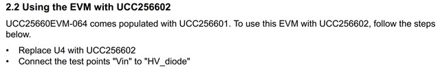
I soldered "Vin" and "HV_Diode" test points together, and fed EVM by 380DC.
it works without changing the chip.
As I understood from our discussion in different thread, using UCC256601 with DC voltage applied to the HV PIN (through series resistors) will lead to incorrect internal HV current source operation and possible fail (what actually I observe in my design).

Thanks.

  • Hi Alex,

    There is no mistake in the EVM.

    In the EVM, energy to the Half bridge is supplied by the External DC supply. Not through the AC Source.  See the connection below.

    In order to showcase the capability of HV startup and X-cap discharge, following circuit is being used.

    As I understood from our discussion in different thread, using UCC256601 with DC voltage applied to the HV PIN (through series resistors) will lead to incorrect internal HV current source operation and possible fail (what actually I observe in my design).

    There won't be any incorrect HV current source operation when you connect HV to DC input. Since HV pin is connected to DC, X-cap discharge is going to be enabled (since zero crossing is not detected) and tried to discharge the DC input during which the IC temperature is going to high. If the temperature of the IC reaches internal OTP, controller will shut down. The rise in temperature depends on the thermal constant of the PCB board where IC is populated.

    Regards

    Manikanta p

  • Hi Manikanta,
    Thank you for explanation.
    I didn't realize the full complexity of the chip's architecture.

    If I understand correctly, _01, _02, _04 versions are able to perform HV startup, but _01 and _04 also contain X-cap discharge current source and control algorithm. Thereby, being fed by DC source, they will activate X-cap discharge accordingly to the algorithm, and heat up itself, transiting to OTP, right?
    The _02 version, will not activate internal X-cap discharge current source, only the source, required to charge Vccp cap, right?


  • Hi Alex,


    If I understand correctly, _01, _02, _04 versions are able to perform HV startup, but _01 and _04 also contain X-cap discharge current source and control algorithm. Thereby, being fed by DC source, they will activate X-cap discharge accordingly to the algorithm, and heat up itself, transiting to OTP, right?
    The _02 version, will not activate internal X-cap discharge current source, only the source, required to charge Vccp cap, right?

    That's correct.

    Regards

    Manikanta P