Other Parts Discussed in Thread: LM74800-Q1, LM74502-Q1, LM7481-Q1,
Tool/software:
Hello,
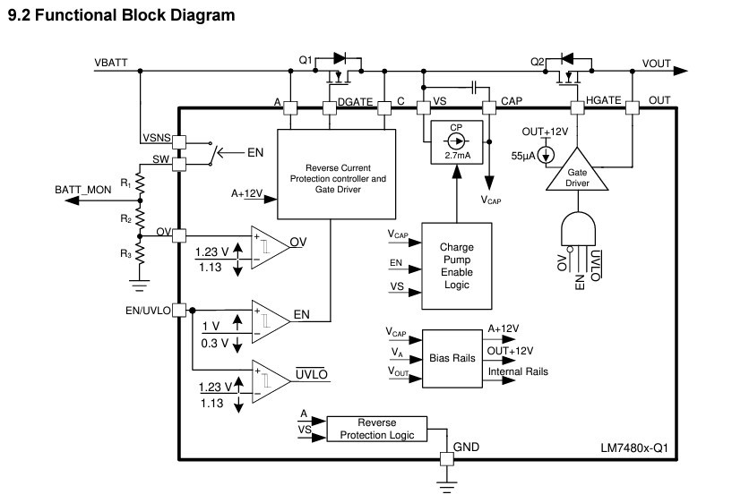
Referring to the image from the datasheet below.
I want to omit Q1, the FET relating to ideal diode functionality.
But use Q2, the FET relating to load switch functionality.
Possibly in a back to back configuration, for reverse voltage protection.
My goal is to provide reverse voltage protection, but to allow reverse current flow.
It would be used on a battery interface, where the battery would be both charged and discharged.
What is the recommended approach?
If Pin A and Pin C are connected together, at the same voltage, and Q1 is not populated, would Q2 operate normally?
Thanks
EDIT: I don't want to use the LM74801-Q1 variation, because i will be using the LM74800-Q1 elsewhere in my design.