This thread has been locked.

If you have a related question, please click the "Ask a related question" button in the top right corner. The newly created question will be automatically linked to this question.

TPS35-Q1: Please review the schematic, and have some questions.

Part Number: TPS35-Q1

Tool/software:

Dear TI experts,

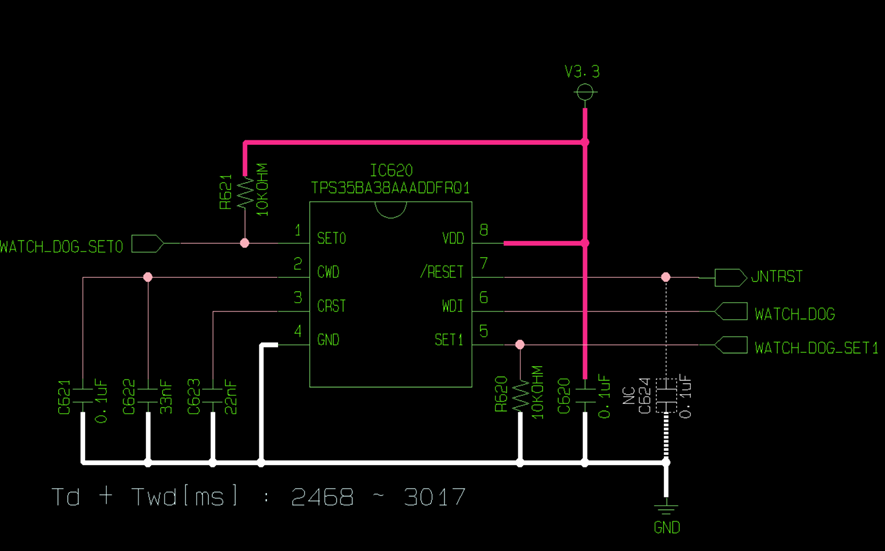
My customer draw their first schematic using TPS35BA38AAADDDFRQ1. Could you review this schematic?

My customer wants to make a watchdog about every 3 seconds. So My customer calculated tD and tWD as follows.

: Reset time delay = tD (sec) = 4.95 × 10^6 × CCRST (F) = 4.95 × 10^6 × 22nF = 108.9ms

: Watchdog timeout period = tWD (sec) = 4.95 × 10^6 × Ccwd (F) = 4.95 × 10^6 × 133nF = 658.35ms -> mutiply 4 for time scaling -> 658.35ms X 4 = 2633.4ms

=> 108.9ms + 2633.4ms = 2742.3ms => about 3 seconds of watchdog time made regarding 10% maximum error rate.

Here are my additional questions ;

1. Please review the schematic especially the passive components.

2. Is my calculation for watchdog time right? or could you suggest other way?

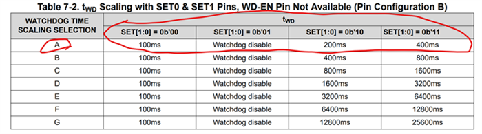
3. How can I set SET[1:0] for midfix "A" device? is the below table is right? -> So I can set SET[1:0] pin both 1 for x4 scaling.

4. What is difference between tWD(Watchdog timeout period) and tWDO(Watchdog timeout delay)? Is it right to use tWD for calculating watchdog time?

5. How can I estimate maximum and minimum error rate (also accuracy) for watchdog time? Is 10% normal value for accuracy?

Please check these issues. Thanks.

Best regards,

Chase

  • Hi Chase,

    1. Any capacitance on the RESET line like C501, this will help to make the RESET timing accurate and not add additional delays. 
    2. You calculation for watchdog timing typ of 2633.4ms is correct. However the accuracy is 20% for the watchdog timing because you are using capacitor adjustable timings and not a fixed internal ratio timing. As well you will need to account for the accuracy of the capacitors when calculating the tolerance of you timeout period. 
      1. I would also like to confirm my understanding, the customer would like the timeout period + the RESET assertion(time RESET is low) time to be 3s?

    3. Yes you are correct, in your current schematic configuration by default SET[1:0] = 0b'01, but my assumption is that when your system is done booting up you bring SET1 = 1 (high) so that SET[1:0] = 0b'11 and you will have a x4 scaling.
    4. The watchdog timeout period is the time that you have to provide a valid WDI falling edge transition for the watchdog (your 2633.4ms). The watchdog timeout delay is the reset time delay (your 108.9ms) which is the time that the RESET is held low after it is asserted from either a failure to provide a valid WDI transition or from the voltage falling below the undervoltage threshold.
    5. Please see answer to questions 2 above.

    Thanks,
    Joshua

  • Dear Joshua,

    Thank you for your support.

    Yes, the timeout period+reset assertion time to be 3s.

    My customer said that it is okay that the time is longer than 3s, but it is not allowd shorter than 3s. so they think that capacitance tolerance and accuracy are important.

    Anyway I will discuss this issue with my customer, and post another thread if I have more question.

    Best regards,

    Chase