This thread has been locked.

If you have a related question, please click the "Ask a related question" button in the top right corner. The newly created question will be automatically linked to this question.

UCD9090A: 电流监控读取不准问题咨询

Part Number: UCD9090A
Other Parts Discussed in Thread: UCD9090, INA196

Tool/software:

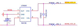
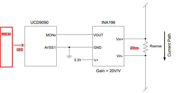
1、电流监控设计如下图,采用UCD9090+INA916的方式,采样电阻是20毫欧

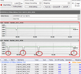
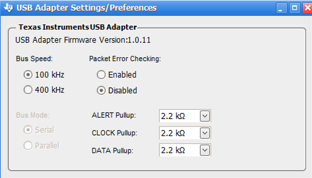
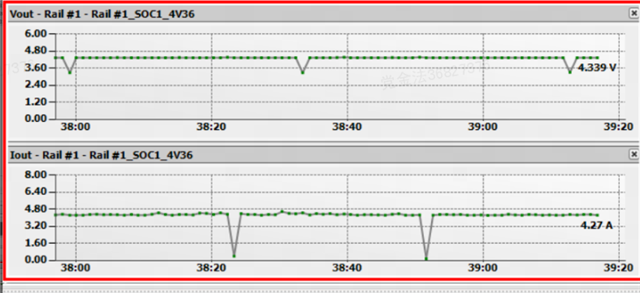
2、当负载电流1A~3A的时候,MCU通过I2C获取UCD9090的电流基本吻合,当电流增加到4A的时候,MCU通过UCD9090获取的电流只有2.3A左右,但是通过上位机(Fusion)读取的电流是4A左右,与实际电流基本吻合

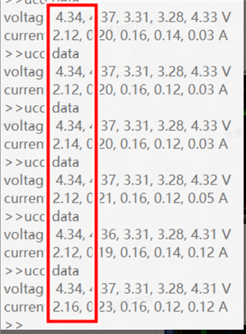
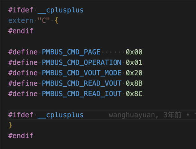
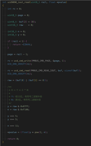
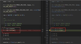
3、MCU是通过读取UCD9090寄存器0x8C获取电流值

为什么MCU读取0X8C获取的电流值有问题,而上位机获取的电流是OK的?

  • 1、The current monitoring design is shown in the figure below, using the UCD9090 and INA916 combination. The sampling resistor is 20 milliohms.

    2、When the load current is between 1A and 3A, the MCU can obtain a stable current reading from the UCD9090 via I2C. However, when the current increases to 4A, the current reading obtained by the MCU through the UCD9090 is only around 2.3A. In contrast, the current reading obtained through the host computer (Fusion) is around 4A, which is consistent with the actual current.

    3、The MCU obtains the current value by reading register 0x8C of the UCD9090. Why is there an issue with the current value obtained by the MCU when reading 0x8C, while the current value obtained by the host computer is correct?

  • Hi,

    I will need to look into this behavior. I will get back to you by or before Monday the 27th.

    Regards,

    Troy

  • Hi,

    Since the correct current is being logged by the device, shown by Fusion getting the correct value from 0x8C register, I suspect something is wrong with how the MCU is requesting or decoding the data over I2C.

    When using I2C to read 0x8C, make sure you send request to read 2 bytes.

    Can you provide the format being used by the MCU for this transaction? 

    Regards,

    Troy

  • Thank you! I just got back from the Spring Festival holiday, so I apologize for the delayed response. I will confirm and get back to you shortly.

  • Hi~

    1、When using I2C to read 0x8C, make sure you send request to read 2 bytes.

        yes,I confirm that the read request is for two bytes

    2、Can you provide the format being used by the MCU for this transaction? 

  • Hi,

    Can you send the values of buf[0], buf[1] and the corresponding decoded value using your code? 0x8C register is linear11 format, and I want to check if your code is decoding this format accurately.

    Regards,

    Troy

  • Hi~THANK YOU

    1、The issue of the MCU reading abnormal current through I2C was indeed caused by incorrect data decoding. The problem was resolved after modifying the code.

    2、Another issue we found is that when the host computer(Fusion) reads the current, there are occasional instances where the current is zero. What could be causing this?

  • Hi,

    Glad to see the abnormal current reading was resolved. I will check about causes of the occasional zero current reading, and get back to you tomorrow.

    Regards,

    Troy

  • Hi,

    Can you provide your schematic and device configuration file (.xml exported through Fusion) to help us determine the cause of the zero current reading?

    Regards,

    Troy

  • Hi,

    You said in your initial post that the sense resistor for the INA196 was 20 milliohms, but in the schematic there is a 100nF capacitor shown in between the VIN+ and VIN- pins instead.

    Can you confirm the current sense setup uses the appropriate sense resistor? If so, can you probe the voltage going on to the MON pin when the zero current occurs?

    Regards,

    Troy

  • Hi

    1、The sensor resistor is 20 milliohms. The schematic of the sampling resistor is on another page. See the figure below. It's just that the schematic I sent does not include the sampling resistor.

    2、I will try to probe it.

  • Hi,

    Thanks for confirming the sampling resistor. Will continue to look into zero current reading, while awaiting MON pin voltage measurement.

    Regards,

    Troy

  • For example, when the load current is around 3.25A, the current collected by the host computer(Fusion) is shown in the figure below. There are occasional instances where the current is zero. The voltage of the sampling channel (MON6)in this circuit remains stable at around 1.3V.

    It seems that the voltage of MON6 is normal. Does the host computer (Fusion) require any special settings?

  • Hi,

    Since the voltage is steady, the zero current instances are likely coming from a communication issue where Fusion attempts to read the current but receives an I2C NACK or invalid data for that polling cycle.

    You can try changing the polling time in Fusion (currently set to 250ms), to see if it affects the number of zero instances. I assume you are using the TI USB adapter to connect to Fusion? You may change the settings on your USB adapter to use 100kHz and disable PEC, to see if that resolves any communication issue that is present.

    Please also tell me what version of Fusion you are using currently.

    Regards,

    Troy

  • 1、changing the polling time in Fusion (currently set to 250ms), to see if it affects the number of zero instances

    -----100ms  1000ms,it did not produce any impact.

    2、You may change the settings on your USB adapter to use 100kHz and disable PEC, to see if that resolves any communication issue that is present.

    ----it did not produce any impact.

    3、i am using the TI USB adapter to connect to Fusion,the version of Fusion is7.6.1

    4、The test environment is shown in the figure below.

  • Hi,

    You can try moving to a newer version of the Fusion Digital Power Designer software, found here: https://www.ti.com/tool/FUSION_DIGITAL_POWER_DESIGNER 

    I will check with our team for other potential fixes to this behavior.

    Regards,

    Troy