This thread has been locked.

If you have a related question, please click the "Ask a related question" button in the top right corner. The newly created question will be automatically linked to this question.

LM25143: 8 phase control or more phase control about buck controller 'LM25143'

Part Number: LM25143
Other Parts Discussed in Thread: LM5137

Tool/software:

Hi TI technical Support Team,

         Good day! we are an electronic engineering team and have some questions about TI multiple phase buck controller "LM25143".

         According to the description in chapter 9.3.17.3 "Single-Output Multiphase Operation",  LM25143 can support 6-phase or more for heavier loading driving.

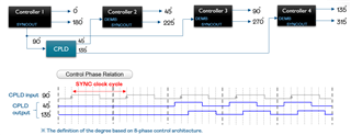
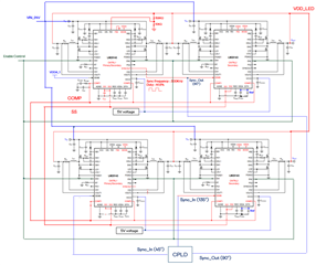
The figure is attached as below to show the connection of 8-phases control architecture we designed,  4 pcs of controllers are needed for our application case, 


       After our experiment, the activity of LM25143 is abnormal. there is not any MOSFET switching activity of each controller.

We guess there should be incorrect connection in our design. 

       We would like to know how to design  8-phase control or more phase control. ex : Hardware pin connection (FB, MODE, SS, COMP, DEMB, SYNCOUT, etc.)

If there is a figure to explain the connection method, it's better for us and If there is any other suggestion, please let us know as well.

Thanks a lot!


  • Hi,

    One thing to note is that Cdith can be removed from each controller and dith be shorted to ground to disable dithering. 

    Additionally can you please confirm what the CPLD block is meant to do? Does it take the input from Sync out and output a clock signal 45 degrees and 135 degrees lagging from 90? Or does it create the two clock outputs, one 45 degrees leading and the other 45 degrees lagging from the 90 degree sync out?

    Thank you,

    Joshua Austria

  • Hi Joshua,

         Thanks for your confirmation! I simply summarized the purpose of CPLD block as below,

    (1)  It  take the input from Syncout of the primary controller and then

          create the two clock outputs for 45 degrees and 135 degrees of SYNC signals in 8 phase-control architecture.

    (2)  Since CPLD has to take 90 degrees SYNCOUT from the primary controller first so

           the activity of 45 degrees and 135 degrees of SYNC signals will be delayed for 2 SYNC clock cycles during power start.

    (3) The relation of SYNC signals is one 45 degrees leading and the other 45 degrees lagging from the 90 degree sync out during normal operation.


    I attached a timing chart as below for your reference.

    One more question,

    which of the following conditions is correct about the configuration of the controller 'LM25143' for 8-phase control?

    (1) One primary controller and three secondary controllers. Or,

    (2) Two primary controllers and two secondary controllers.


    Thank you!

    Harvey

  • Hi Harvey,

    I will have to check internally with the team if this is ok. Before I ask however, is there any way to capture the waveform of the CPLD signals and show them compared to the output clock of the primary controller on the bench? If the oscilloscope can capture this data I want to make sure that the signals that are stated to be coming from CPLD are sufficient and able to drive the DEMB pins of the secondary devices.

    Theoretically, I believe both cases are valid to control the 8 phase controller, but I will check internally as well to confirm this. I believe your system is currently designed to employ case 1. Is there a reason you are interested in evaluating case 2?

    Thank you,

    Joshua Austria

  • Hi Joshua,

           Our system is currently designed to emply case 1. The waveform of the CPLD signals is attached below for your reference.

           Since the operation condition example described by LM25143 specification is a primary controller plus a secondary controller so we just would like to know which is the correct condition,case 1 or case2 ?  If case 1 is the better case, we will choose case 1 for our design.

    Thank you,

    Harvey

  • Hi Harvey,

    Thank you for sharing this. I will check with the team and get back to you soon. 

    Thank you again for your patience,

    Joshua Austria

  • Hi Harvey, 

    There should not be much of a difference between either case. We recommend debugging with one controller first to see if you can get that working. Once you have the results from one controller, I would be happy to review the resulting waveforms with you. From there the plan is to increase the controller count to see what the issue may be.

    Thank you,

    Joshua Austria.

  • Hi Joshua,

    Thanks for your reply!

               Before debugging, I would like to confirm whether the connection method of our design is correct theoretically, 

    especially the schematics of case 1 I shared 3 days ago. you can also refer to the attachment below.

    If it's correct, we will base on the architecture to plan relevant experiments. 

    Thank you,

    Harvey

  • Hi Harvey,

    From our perspective we do not see any issues with the schematics of case 1 that was shared before. Theoretically, it looks to be fine but there could be layout issues or some other issue we are not able to see from the schematic view that is causing the devices to not work. 

    I will reaffirm that we recommend the debugging steps as listed above to ensure the device operates properly with a single controller, so we can begin to determine the root cause of the issue.

    Thank you,

    Joshua Austria

  •  Hi Joshua,

          4 phases control is normal. we had done an experiment about 8 phases control, that is, change R,C value of the compensation network,

    the controller does work. However, there still is some issues, we need some time to collect information for future discussion.

          Now, we would like to know :

    (1) How to calculate R,C value of the compensation network for 8 phases control or more phases control?

         Do you have software tool which can be shared to us for R,C value calculation?

    (2) Is there the upper limitation about phase number increment? ex : 12 phases.

    (3) If the hardware configuration of 8 phases control is set as 2 primary controllers and 2 secondary controllers,how to connect

         the compensation network?especially the connection method between 2 primary controllers.

    [note] basic operation condition : V input : 24(V), V output : 10(V), I output : 90(A), switching frequency : 300KHz

    Thank you,

    Harvey

  • Hi Harvey, 

    Thank you for performing that debug. I will reach out internally with the team and respond once I hear back.

    Thank you,

    Joshua Austria

  • Hi Joshua,

    Excuse me, I would like to know whether you get the information about the operation method of buck controller 'LM25143', like R,C equation of compensation network, etc. 

    Thank you,

    Harvey

  • Hi Harvey,

    I am still awaiting the team and will reply here once I hear back.

    Thank you for your patience,

    Joshua Austria

  • Hi Joshua,

    About questions we mentioned last time, have you received any news from TI internal team?

    If possible, could you let us know how to calculate R,C value of the compensation network for 8 phases and 12 phases first?

    Thank you,

    Harvey

  • Hi Harvey,

    I heard back from the team. Here is a document on multiphase current-mode control: https://www.how2power.com/pdf_view.php?url=/newsletters/2412/articles/H2PToday2412_design_TexasInstruments_part%202.pdf

    Equation 17 in particular is what should be paid attention to for loop compensation and is the main difference when it comes to operating multiphase operation.

    Thank you,

    Joshua Austria

  • Hi Joshua,

    Thank you for your support.

    I found a deisgn example of LM5137 in the document you provided. And, I have confimred that LM5137 and LM25143 are same family.

    I have some questions as below,

    (1) May I calculate component value of the compensation network of LM25143 with equation 17? 

    (2) if the answer of itme (1) is yes, A few controller parameters has not been mentioned in LM25143 specification, like mc = 1.275, etc.

         how about mc value for LM25143? May I use directly controller parameters  from page 6? 

    (3) Could you give us more advice about component value calculation of LM25143?  

    Thank you,

    Harvey

  • Hi Harvey,

    1) Yes.

    2) Yes you can use the values from page 6 that pertain to the controller.

    3) All the advice for the component calculation of the LM25143 should be on the document provided and the calculator here.

    Thank you,

    Joshua Austria