
- Ask a related questionWhat is a related question?A related question is a question created from another question. When the related question is created, it will be automatically linked to the original question.
Tool/software:
Hi guys,
I've recently got to know the DC-DC TPS55288 buck-boost series which in theory is perfect for my application.
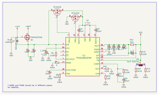
However, I'm struggling with it and I'm reaching here for some guidance and help. I've attached the first design that I've developed based on the recommendations on the datasheet. It's not yet the final version that I want (I2C version) but it should in theory be very similar.
The problem that I have is that if I select the output voltage to be 12V when the input is below 3V the L8 4.7uF coil starts to make a lot of noise and the input current also increases a lot even without no load attached. Is this an expected behaviour? For context what I'm trying to achieve is a buck-boost topology where I could control the output voltage between 5V up to 12V (I no longer need the 22V output). Regarding the input, it can change from different application and can be directly connected to a solar panel. In which during night hours an internal 4.2V LiPo battery would take place and be the input instead. So my input range would need to be as low as the 2.7V up to 26V. This part number seems to be ideal since it can handle all of this variaty of input voltages and can be configured for the desired output voltages.
My plan b is to use the adc of the mcu to read the input voltage and the having a TLV61048 booster and a buck controlled also by the mcu to be able to control the output voltage.
Thank you for the support,
Best regards,
Fernando Fontes


