


Other Parts Discussed in Thread: TPS61175,
Tool/software:
I am following application report SLVA452 ( Compensating the Current-Mode-Controlled Boost Converter) to understand how to determine the compensation network values. The example provided is for TPS61175 but most concepts are similar.
I created an Octave script to perform the analysis. The results I obtained are identical or very close of those of the example. This is the gain of the frequency response, which closely matches the gain on Figure 3 of the app. report:

I copied the script and made adjusts to calculate the compensation network for TPS61178. Below an excerpt of the script with the input parameters:
Vin = 10;               % Worst case (Vin min)
Vout = 19;              % Output voltage
Iout = 1.6;             % Output current
Eff = 0.97;             % Estimated efficiency
fSW = 636000;           % Switching frequency
L = 5.6e-6;             % Inductor
Cout = 5e-5;            % Total output capacitance
Resr = 3e-3;            % Output capacitance ESR
Rdson_ls = 0.022;       % From data sheet, Fig 11, worst case
Rsense = 0.083;         % From data sheet, typical value

D = 1-Vin/Vout;         % Duty cycle
Rout = Vout/Iout;       % Output equivalent resistance

Sn = Rsense*Vin/L;
Se = 0.06*Rdson_ls*fSW/(1-D);
Notice Se uses the Eq. 21 of the data sheet:

Here the graph of the gain:

I found that peak at 300kHz suspicious. I then noticed Sn > Se:

Notice values of output capacitance and inductance ( 5.6uH and 50uF) are typical for Vin, Vout, Iout, swiching frequency and ripple current of 30% (ish).
I made Se = 5*Sn just to see what happens and this is what I get:

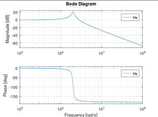
For comparison, this is the bode plot of He(s) for TPS61175...

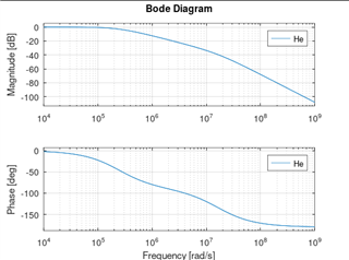
..., the bode plot of He(s) for TPS61178 with Sn > Se...
..., and the bode plot of He(se) for TPS61178 with Se = 5*Sn:
This is the complete Octave script for TPS61178 (it may work with Matlab but I am not sure):
% Calculate gain of power stage o TPS61178

clear all

Vin = 10;               % Worst case (Vin min)
Vout = 19;              % Output voltage
Iout = 1.6;             % Output current
Eff = 0.97;             % Estimated efficiency
fSW = 636000;           % Switching frequency
L = 5.6e-6;             % Inductor
Cout = 5e-5;            % Total output capacitance
Resr = 3e-3;            % Output capacitance ESR
Rdson_ls = 0.022;       % From data sheet, Fig 11, worst case
Rsense = 0.083;         % From data sheet, typical value

D = 1-Vin/Vout;         % Duty cycle
Rout = Vout/Iout;       % Output equivalent resistance

Sn = Rsense*Vin/L;
Se = 0.06*Rdson_ls*fSW/(1-D);
%Se = Sn*5;


fP = 2/(2*pi*Rout*Cout);
fESR = 1/(2*pi*Resr*Cout);
fRHP = Rout*(1-D)^2/(2*pi*L);

s = tf('s');

He = 1/(1+ s*((1+Se/Sn)*(1-D)-0.5)/fSW + s^2/(pi*fSW)^2);
G0 = Rout*(1-D)/(2*Rsense);
Zesr = 1+s/(2*pi*fESR);
Zrhp = 1-s/(2*pi*fRHP);
Pout = 1+s/(2*pi*fP);
%Gps = G0 * He * Zesr * Zrhp / Pout;
Gps = G0 * He * Zrhp / Pout;

FMIN = 10;
FMAX = 1000000;
WRANGE = {FMIN*2*pi, FMAX*2*pi};
[mag, w] = bodemag(Gps, WRANGE);
f = w/(2*pi);
magdb = 20*log10(mag);
semilogx(f,magdb)
grid on
title('Gain of the frequency response with TPS61178')
xlabel('Frequency (Hz)')
ylabel('Power stage gain (dB)')
The script requires the control package (pkg load control) to work.


