This thread has been locked.

If you have a related question, please click the "Ask a related question" button in the top right corner. The newly created question will be automatically linked to this question.

TPS1HC100-Q1: Function of the nFault Pin

Part Number: TPS1HC100-Q1

Tool/software:

Hello,

I'm testing the TSP1HC100-Q1 to switch on a +24V Power Supply to a Load resistance of approx. 40Ohm, accordingly 600mA flows through the device. Behind the Switch there is a 100µF Capacitor. 

I set the current limit level to approx. 1A with a 51kOhm resistor. The Diag_En Pin is set to high and I want to switch the power supply on with the Enable Pin. I'm monitoring the Fault Pin with an oscilloscope.

 In the moment I set the Enable Pin to high and the Switch is activated the fault pin is pulled to low for a short time and then set high again . 

I didn't expected that behaviour because the Load Current is under the ILIM Value. Can you please explain why the nFault Pin is pulled to low?

purple channel = nFault Pin

light blu channel = enable Pin 

Green channel = load current

Blue Channel = Voltage behind switch

Best Regards,

Dominik 

  • Hello Dominik, 

    Is the Blue channel VBB? 

    If it is can this be tested with VBB high before the device is enabled?

    BR, 

    Alan

  • No it's the voltage at the VOUT Pin. The VBB Pin is connected to an external +24V power supply and is permanently activated. I didn't monitored the VBB voltage with the oscilloscope. 


  • Dominik, 

    I will look into this and get back to you when I have more information.

    BR, 

    Alan

  • Hi Alan, 

    i have done a little mistake at the measurement. The capacitors were not connected to the current path which I measured. So the inrush and load current of the capacitor is not seen on the last picture.

    Due to this i repeated the measurement with the cpacitors connected.
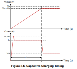
    The current limit is still set to approx. 1A with a 51kOhm resistor at the ILIM Pin. In the switch on moment the current rises to 1.5A and is above the 1A current limit. This explains why the device returns a fault. Now i understand why there is a fault. But I didn't understand why the capacitor isn't charged with a constant Current ILIM.

    I expected something different, because the device should load the capacitor with a constant current. This is described in the datasheet chapter 8.2.2.1.
    Why is the current not limited to 1A in my measurement?
    Is there anything I need to consider that the current limitation work properly?

    BR, 

    Dominik 

  • Hello Dominik, 

    The TPS1HC100 datasheet displays a figure for capacitive load charging to ensure application functionality. From your waveform it looks like the device hits the peak current enabling into permanent short (ICL_ENPS), which is around 2 x CL then after the cap is charged it settles. This is what is displayed in the datasheet. 

    In addition, there is an application report on driving capacitive loads 

    https://www.ti.com/lit/an/slvae30e/slvae30e.pdf?ts=1737489290778

    BR, 

    Alan