This thread has been locked.

If you have a related question, please click the "Ask a related question" button in the top right corner. The newly created question will be automatically linked to this question.

TPS26630-33EVM: TPS26635 switched off unintentionally

Part Number: TPS26630-33EVM

Tool/software:

Hi TI team,

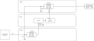
I do have a design which consists of two TPS26635 on the same 24V Powersupply.

On the first path eFuse1 there is a 24V to 5V DC DC converter which powers the CPU system

On the second path eFuse2 there is a high current load ( for checking my design I connected a electroic load to the output of the eFuse2)

The eFuse2  Shdn pin is controlled by an GPIO from the CPU, which allows me to switch on/off the attached device on eFuse2.

Here is what I tested and what happend:

1. I configured the electronic load with e.g 30ms at 50mA and than 10ms at 5A in an endless loop.

2. I enabled the eFuse2 by setting the GPIO from the CPU high.

3. Let the system run 

Result system works fine.

4. I started toggling the eFuse2 Shdn pin approx 2times a second

Results

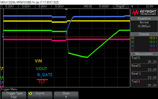
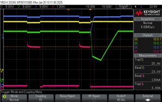
After a few toggle ( switch on/off) on the efuse2 it happend that the efuse1 switched off the 24V to the CPU DC/DC and the system crashed.

Sometimes it tooks a lot of toggles ( >20) sometimes it happend at the first time.

From what I read here in the forum it looks like the efuse2 switched of because of reverse current trigger .

How can I fix this ?

  • Hello Markus,

    Welcome to e2e.

    It can be reverse current detection. Can you verify this probing VOUT, VIN,B_GATE and FLT signal.

    Do you need reverse current protection for your supply?

    You can always remove reverse current blocking by removing and shorting the external FET.

    Thanks

    Amrit 

  • Thanks for the quick answer.

    I do not need necessarily reverse current protection but I need reverse polarity protection

    Here is what I measured on the Signal you suggested.

    I dont see the FLT signal going low, but clearly see the Outvoltage dropping to 10V

  • Hello Markus,

    The dip in VOUT looks like device is in current limiting or power limiting and going into protection.

    What's the mode pin connection? Is it auto-retry or latch-up?

    Can you check the IIN current to verify?

    Thanks

    Amrit 

  • Hi Amrit,

    it is running in auto retry mode.

    I attached the below new measurement, the red signal shows the pulsed current   through efuse 1 .

    I dont think that it is power/current limitting because as i wrote it happend on efuse1  when  efuse 2 is switched off.

    If I would remove the back current /polarity protection, what would happened to the efuse itself, would it survive a wrong power supply polarity ?

    Is there any chance to trim the behavior of the reverse/polarity protection that it does not react on short voltage differences ?  What about on adding a RC circuit to the IN_sys ?? 

  • Hello Markus,

    From IIN it looks like it's going more than the current limit.

    Can you check increasing the ILIM value through RILIM resistance?

    Thanks 

    Amrit 

  • The current which is shown in the image above does not show the current from the efuse which causes the fault! Please look at my blockdiagram.

    The current you see in the picture is the one through efuse2 ! 

    Through efuse1 the current is about 400mA, and the Powerlimit is set to 80W, 

    When I switch off this efuse2 by pulling the shdwn pin low the 24V on VOUT of the Efuse1 drops down to 10V ( you can see this in above image green signal) !

    So why does this happens ?? 

  • Hello Markus,

    Sorry for the confusion.

    This is reverse current detection then since BGATE is closing.

    You can verify this by removing external FET. short it and check if you see this issue.

    You can keep more cap at input so VIN drop will be delayed which can avoid reverse current flowing from OUT to IN.

    Thanks 

    Amrit 

  • Hi Amrit,

    here is a image which shows the VINsys, Vout, the Shdn pin and the current.
    yellow = VIN_sys (efuse 1)

    blue = VOUT ( efuse1


    green = Shdn pin ( efuse2)

    red = current (efuse 2) 

    After these measurements I  added more capacitance to the  Input increased from 1uF to 20uF  but result is the same !

    If I remove the FETs as you described I will lost the rerverse & polarity protection, would the efuse survive than a reverse polartiy connection ?

    MArkus 

  • Hello Markus,

    Can you attach the waveform? I don't see it in previous thread.

    What's the output cap on eFuse-1

  • Outputs capacity on efuse1 is about 20uF

  • Hello Markus,

    We can try isolating the fault.

    Please follow the debug steps.

    1. Let's confirm that there is reverse current blocking. Please measure the VOUT and VIN_SYS in waveform. You can also check by shorting the external FET if same fault is happening (not a solution just to isolate the fault). If we are confirmed that this reverse current blocking, you can try with increasing the CIN. Please keep CIN> COUT.

    2. If reverse current blocking is not the case, please check input current to eFuse-1. I don't see that in above waveforms.

    Thanks 

    Amrit