This thread has been locked.

If you have a related question, please click the "Ask a related question" button in the top right corner. The newly created question will be automatically linked to this question.

TPS25750: USB-C PD hub with charging and data ports.

Part Number: TPS25750
Other Parts Discussed in Thread: TUSB8043A, TUSB8044A, , TMUXHS4212, TUSB1042I, TPS25751

Tool/software:

Hi,

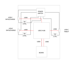
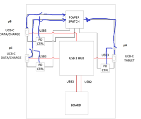
I’m working on a project that requires a 4 port USB3 hub. The upstream and two of the downstream ports shall be USB-C ports. The others downstream ports will be used for communication with on board devices. The upstream USB-C port will be connected to a tablet. The two USB-C downstream ports we want to be used as a data or charging port interchangeably, meaning we want to connect a USB-C charger on one and USB-C flash drive on the other. The charger will charge the tablet while we download data from the tablet on the other port. For USB 3 hub I think to use TUSB8043a OR TUSB8044A. PD controller probably TPS25750. USB MUX TMUXHS4212 or TUSB1042I.

Can you recommend how to implement the power switching circuit that will be sitting between the two USB-C DFP and the USB-C UFP to be able to charge the tablet or sink power from it.

Here is a diagram of the device.

  • Hi D. Dimitrov,

    First off, let's make sure you selected the correct IC's.

    For the PD controllers, you should not be using the TPS25750, and should instead use the TPS25751 or TPS65987DK. If you need TBT on any of the ports, you will need to use an Intel Reference design, and should contact them. If you need DP alt mode, you should use the TPS65987DK, and for USB only you can use the TPS25751.

    The TPS25750 is an older part and does not have the latest support or features. The TPS25751 is the direct successor.


    Regarding the charger, there are a couple ways it could be done, but I can only provide some suggestions. There are also a lot of factors that need to be considered, including but not limited to:

    • Power roles of each port
    • Power levels of each port
    • Switching power priority
    • Control of power paths
    • regulation of output power

    If I understand correctly, you want to have two possible power input options, pB or PC, and power will be output from pA.

    Does the system have another source of power, or is there always guaranteed power from one of the ports? A 5-V contract is required for any source port, and must be supplied from somewhere.

    The main thing to understand about each port PD controller is that they can be configured to act a certain way, but will act independent of each other without the intervention of an external MCU/EC to control them. Another comment to make is that the port power path will pass through a power switch controlled by the PD controller. In the case of the TPS25751D, it has an internal High voltage power path that can be used for sinking and sourcing. For sourcing, the PP5V pin must be supplied with a 5-V rail.

    For example, if a Type-C source is attached to pB, it can be configured to sink power and provide it to the system side of the PD controller switch by itself. pC can be configured to do the same, but each will act independent of one another.

    To have some from of "smart control' in the Power Switch block, an EC or something similar may be needed to manage the power paths.

    Regarding the pA Source port, this could get more complex. If you only need 5-V, and only ever plan on Sourcing, you can use the PP5V power path to source 5-V contracts. If you do plan on negotiating many voltages from pA, you will need a dedicated DC-DC converter to generate said voltages.

    Regarding the switching circuit, you could potentially set a couple switches controlled by an EC to know when to divert power, and use I2C to monitor the ports. Or if both ports are always sinking, you could create some form of RCP or diode circuit that would only let 5-V pass from the sink ports to the source ports. The main thing to understand is that the PD controllers for each port work independently of each other, and you will need to account for that in your system design.

    The biggest issue you will probably face is ensuring the sourcing port advertises the correct power. You can change the power being advertised by the source port using I2C register writes, and you can read from "sinking" ports to determine what contract they have negotiated, but you will need some from of EC/MCU to handle the I2C communication if you do not have a guaranteed non-USBC PD power source.

    Thanks and Regards,

    Chris

  • Hi Chris,

    Here is an updated diagram with your suggestions.

    I haven’t figured out all the details yet, but here is a rough algorithm of how this should work:

    In “normal” mode the system will draw power from the tablet. The UFP PD controller will be set to sink power mode. The two DFP PD controllers, on Port 1 and 2, will be set in source mode.

    The power switches will connect the VBUS from tablet to VBUS on port 1 and 2.

    Let’s say the charger is plugged in on Port 1, the MCU will detect the event.

    The MCU will configure the power switches so that it applies a 5V from BUCK-BOOST regulator to VBUS on Port2, and connects only VBUS port 1 to Tablet VBUS.

    The MCU will configure the Port 1 PD controller in sink mode.

    The MCU will configure the Tablet UFP PD controller in source mode.

    The charger and Port 1 PD controller will communicate the PD contract – let’s say 20V/3A.

    Before the charger applies the 20V to the VBUS on port 1, the MCU will pass the PD contract from the charger (20V,3A) to the Tablet UFP PD controller.

    Once the new PD contract has been accepted from the tablet the MCU will pass this to Port 1 PD controller so that the charger can apply the 20V and start charging the tablet.

    There may be some timing and/or sequence constraints that I don’t know yet, but hopefully, we can meet them with the suggested hardware.

    If you see any issues with the suggested flow and or hardware let me know.

  • Hi D. Dimitrov,

    Most of the system functionality will depend on the MCU to control the ports, I can describe some of the controls you can use and the PD behavior.

    For each port, you can modify what voltages are offered as a source by updating the Transmit Source Capabilities Register.

    You can do the same for the sink contracts through the Transmit Sink Capabilities Register

    You can modify the port role using the Port Config and Control registers.

    The Status register reports connection status and connection type.

    The TRM describes the registers in detail. Some will renegotiate the port contract on changing the register, but for others, you must send a command to disconnect and renegotiate the port in order for changes to come into affect. Otherwise, the port will maintain it's current connection.

    All the ports can be configured with a default configuration as you described, and then be updated by the MCU during certain events.

    One thing that the EC will need to do is to manage the power in and power out, and make sure the sourcing ports never offer more power than they system is sinking in. Also you will need to manage any switching of system power from one port to another if that happens.

    One key thing to understand is that all sourcing PD contracts must start with a 5-V contract before negotiating and providing higher voltage contracts.

    For sourcing to the UFP port, it might be necessary to have a dedicated DC-DC converter.

    Thanks and Regards,

    Chris

  • Hi Chris,

    For sourcing to the UFP port I was hoping to use only the charger and connect the VBUS charger to VBUS UFP.

    Alternatively, the simpler options will be to use dedicated charging and data ports. Do you have an evaluation board or schematic for a USB-C PD passthrough connection?

    Thanks,

    Dimitar

  • Hi Dimitar,

    Unfortunately, we do not have an EVM or reference board for USB-C PD passthrough, and I have not seen it done with our solution. The biggest challenge with passthrough is syncing the Sink and Source ports to advertise and negotiate power within the timings required by the PD spec. It is not something trivial, and I have not seen it done with the TPS25751. Typically source ports will have dedicated DC-DC's to manage the voltage transitions per port. If you are only doing 5-V sourcing only, this may be easier, but you still run into the challenge of managing system power level and making sure you do not advertise too much power.

    Thanks and Regards,

    Chris

  • Hi Chris,

    Wow. Somehow, I imagined the passthrough to be the simpler option—just connect the dedicated charging port's VBUS and CC pins directly to the UFP (tablet) port and let them figure it out. In that case, the UFP PD controller would be in parallel with the Charger PD and tablet PD controllers, and I'm not sure how that would work.

    This USB-C PD seems to be quite a challenge Blush

    Regards,

    Dimitar

  • Hi Dimitar,

    Yeah, when we have looked into it in the past, it has proved fairly challenging and non-trivial.

    The main reason we do not just route the CC-lines through is because the Source will advertise power to the system, and the Sink will request power based on it's own capabilities, not taking the "passthrough" portion into account. Some use cases have the passthrough system desiring non-trivial amounts of power (a couple watts), so there needs to be someway to advertise less power to the final sink port so the system can draw power from the source.

    In addition, there are some basic requirements for USB-C PD negotiation for timing that further complicate the system. The main one I can think of is that a 5-V contract is always the initial contract, and then a higher voltage is required, meaning you will have to have the "passthrough" ports on the system communicating with one-another. This is by no means be impossible, but it is something that we do not have a reference design for, and would require some effort with the EC/MCU code and system architecture.

    Thanks and Regards,

    Chris