This thread has been locked.

If you have a related question, please click the "Ask a related question" button in the top right corner. The newly created question will be automatically linked to this question.

BQ24600: Charging Current too high

Part Number: BQ24600

Tool/software:

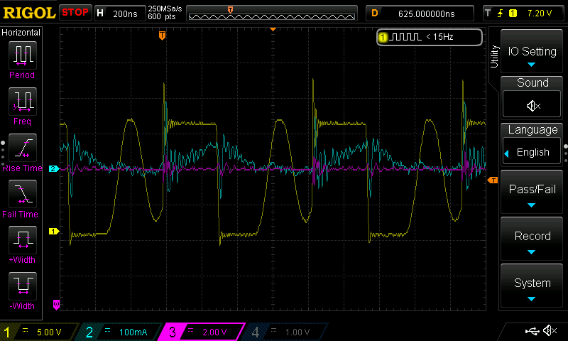
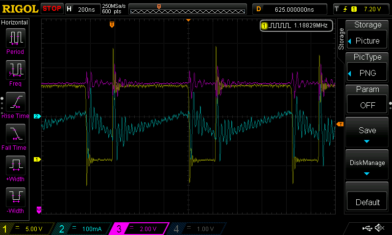
I am a bit confuse with the charging current of my setup. I am trying to charge at 85mA but resulting charging over an Amp.
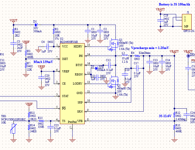
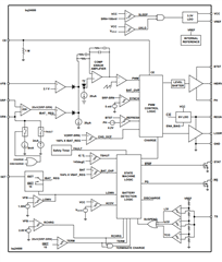
First of all, we are using a small 3S 150mAh battery. We want to have a safe pre-charge so since the "The minimum pre-charge current is clamped to be around 125 mA with default 10-mΩ sensing resistor." as stipulate at page 11, we have use a shunt of 82mOhms to give more gain and lower the pre-charge to about 15mA (1/10C of our small battery). We should now have a safe pre-charge. But despite this above sentence, there is no sign of this behavior in the Functional Block Diagram

Plus there is not much info about the changing the shunt value.
Can we really change the shunt value or we should keep the 10mOhms?

If we are stuck with the default value, I guess that this chip if for battery that are at least 1.25Ah to have a safe 1/10C pre-charge?

So what is wrong with our design?

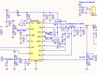
Thanks for your help

  • Hello Mathieu,

    I'm reviewing your schematic, and will provide an update after I gather more information.

    Best Regards,

    Christian.

  • Have you seen anything wrong? Thanks

  • Hello,

    We were out off office on Monday 1/20, response may be delayed. Thank you for your patience

    Best Regards,

    Christian.

  • Sorry to bother you with that but we really want to understand what we see to be able to launch our production with that charger.
    Thanks

  • Hello Mathieu

    I'm sorry for the delay, We typically don't recommend using a current sense resistor greater than 20mohm due to higher conduction loss. Based on your calculation you should be getting around 85mA of charge current. Can you confirm that the voltage measure on ISET is 139mV?

    Best Regards,

    Christian.

  • I confirm that the ISET configuration is correct, but we're seeing excessive current draw when using the 82 mΩ resistor. However, after switching to a 30 mΩ resistor and adjusting the ISET voltage divider accordingly, the charger operates correctly, with a minimum precharge current of around 42 mA. This current seems quite high for our 150 mAh battery. It appears there is a narrow operating range between using 30 mΩ and 82 mΩ shunt resistors. Since this issue seems to originate from the chip itself, we are hesitant to rely on the 30 mΩ resistor as well, as it might be on the edge between a functional and non-functional design.

  • Hello Mathieu,

    If you use a 82mohm inductor, with a 22uH inductor and 7uF output capacitance, do you see any change in the charge current regulation?

    If this does not work, the sense resistor may be too high, and this charger won't be able to fit your design requirements. I can recommend other chargers if it does not.

    Best Regards,

    Christian.

  • Hello Christian,

    Thank you for your help.

    We tested lowering the inductor to 2.2µH while keeping both 10µF capacitors, and it worked fine. Now, we have set the shunt to 60.4mΩ, kept the 2.2µH inductor, and only one 10µF capacitor, and it still works well.

    However, we have another 58.8µF capacitor located about 12mm farther from the charger output. Given this setup, how can we ensure that the charger will always operate reliably?

    Are there specific measurements we should take (e.g., voltage ripple, switching node behavior, current waveform, etc.) to confirm stability and proper regulation? Would you recommend additional layout optimizations or other checks to guarantee long-term reliability?

    Best regards,
    Mathieu

  • Hello Matieu,

    Yes, If you can provide  some waveform captures of the voltage ripple, inductor current, and switch node when the device is operating at highest power close to fully charge and when the device is operating at lowest power setting (precharge). I can check if I can see any major concerns.

    Best Regards,

    Christian.

  • Hello Christian,

    Attached are the waveform captures as requested.

    • Yellow: Switching node
    • Blue: Inductor current (measured with a Rogowski CWTUM/06/B probe in AC mode)
    • Pink: VBATT

    The first screenshot is in precharge and the second is in normal charge. Do these provide sufficient information for you to assess whether our setup is safe for production, or would you need any additional details?

    Looking forward to your feedback.

    Best regards,
    Mathieu


    Precharge

    Charge

  • Hello Mathieu,

    Do these provide sufficient information for you to assess whether our setup is safe for production, or would you need any additional details?

    I don't see any obvious issue on why this would not be safe for production.

    Best Regards,

    Christian.

  • We truly appreciate your help. This is wonderful news for us!