Other Parts Discussed in Thread: BQ40Z50
Tool/software:
Hi
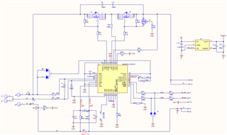
1. When using the BQ40z50 gauge, can the PBI pin of the guage be used to power the EN pin of the LDO to control the opening and closing of the LDO? If PBI can power the LDO pin, can a 51k pull-up resistor be connected as shown in the Figure 10?
2. Is the PBI pin of the gauge only low when the guage is turned off, otherwise the voltage of PBI will always be equal to VBT or VCC voltage