This thread has been locked.

If you have a related question, please click the "Ask a related question" button in the top right corner. The newly created question will be automatically linked to this question.

TPS6594-Q1: nRSTOUT Power-good Window default value

Part Number: TPS6594-Q1
Other Parts Discussed in Thread: DRA821

Tool/software:

Dear Team,

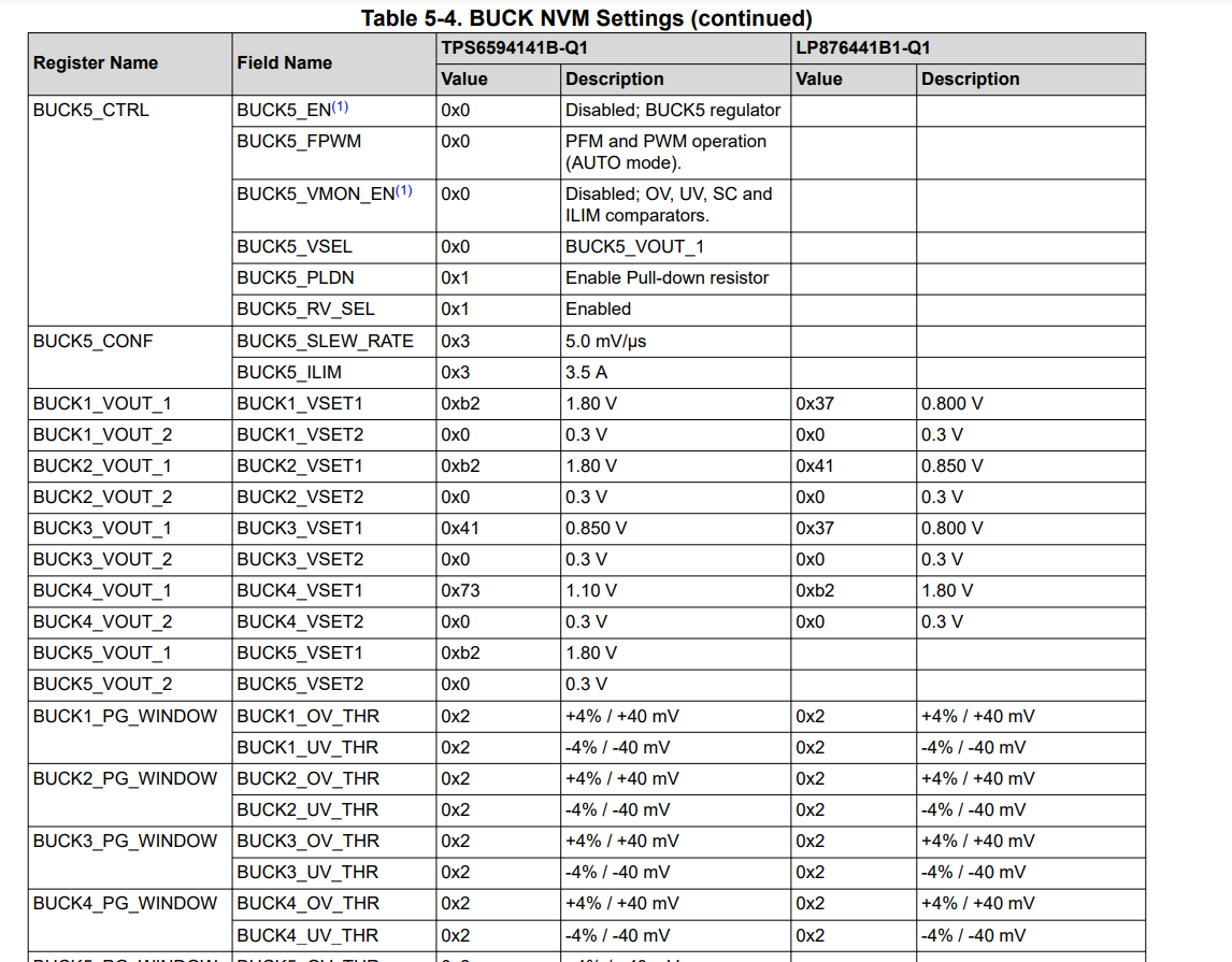
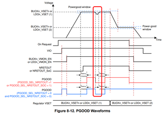
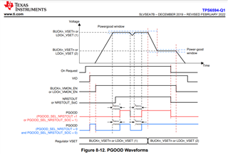
My customer is evaluating the TPS6594-Q1 for powering to DRA821. They use nRST_OUT output of the TPS6594-Q1 for PORz signal of the DRA821.
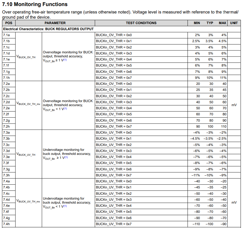
This nRSTOUT monitors BUCKn_VSETn or LDOn_VSET, and goes low if the BUCKn_VSETn or LDOn_VSET fall out of the Power-good Window range.

Can you let us know the default value of this Power-good Window, default value of the BUCKn_VSETn and the LDOn_VSET, please?

Best Regards,

Koshi Ninomiya

  • Hello Ninomiya-San,

    So there's two User's Guides for powering the DRA821:

    Single PMIC User's Guide

    Dual PMIC User's Guide

    Can you let us know the default value of this Power-good Window, default value of the BUCKn_VSETn and the LDOn_VSET, please?

    This waveform explains on how the PGOOD signal behaves if a GPIO is configured for PGOOD output. It does not control or trigger a reaction from the PMIC.

    You are correct that the BUCKn/LDOn_VSET is what dictates the output voltage of the power resources and when the voltage monitors are on, they are comparing this VSET value from the OV/UV_THR. If the output voltage goes outside of this range the PMIC will begin the power down and pull the nRSTOUT. I hope that makes sense, here's a screenshot from the Dual PMIC User's Guide that shows some of the VSET & OV/UV settings, you can find the information the User's Guides above.

    BR,

    Nicholas McNamara

  • Hi Nicholas-san,

    Thank you for your response.
    My customer has a question about " -4% / -40mV " of BUCK1_OV_THR of Table 5-4. BUCK NVM Settings, for example.
    BUCK1_OV_THR is " +4% / +40mV " at the setting value " 0x2 ". They think that buck1 of the TPS6594 is 1.8V output. If the setting value 0x2 is set to +4% = +72mV? Or is it set to +40mV?
    What is the meaning of " +4% / +40mV " with the setting value 0x2?

    Best Regards,

    Koshi Ninomiya

  • Hi,

    due to US holiday on Jan 20th the device expert is out of office. Please expect a delay in response.

    regards,

    Niko

  • Hello Ninomiya-san,

    Thank you for your response.
    My customer has a question about " -4% / -40mV " of BUCK1_OV_THR of Table 5-4. BUCK NVM Settings, for example.
    BUCK1_OV_THR is " +4% / +40mV " at the setting value " 0x2 ". They think that buck1 of the TPS6594 is 1.8V output. If the setting value 0x2 is set to +4% = +72mV? Or is it set to +40mV?
    What is the meaning of " +4% / +40mV " with the setting value 0x2?

    The information in the datasheet doesn't use the +#% /+##mV, it's just a compact display of information demonstrating the nominal value of the OV/UV.

    The percentage corresponds to an output greater than or equal to 1V, so you are correct that the default OV setting of buck1 is 72mV over the output of 1.8V.

    The +##mV corresponds to a power output of less than 1V.

    A single register value can correspond to two thresholds, but the final value OV/UV_THR depends on the value output value of the power resource. We place both values here in the User's Guide because a user can change the output of the power rail to something under 1V, or something over 1V.

    Hope that helps you and the customer, any other questions?

    BR,

    Nicholas McNamara

  • Hi Nicholas-san,

    The customer understood that the OV/UV threshold corresponds to an output voltage.

    They want to confirm one more thing about the NRSTOUT or NRSTOUT_SoC of Figure 8-12. PGOOD Waveforms.
    The redo frame in the figure below shows that the output of the NRSTOUT or NRSTOUT_SOC is not turned off even though BUCKn_VSETn or LDOn_VSET is outside the Powergood window (PGOOD is turned off during outside the Powergood window).
    Why does the NRSTOUT or NRSTOUT_SOC not turn off when the BUCKn_VSETn or LDOn_VSET is outside the Powergood window?

    Best Regards,

    Koshi Ninomiya

  • Hello Ninomoiya-San,

    They want to confirm one more thing about the NRSTOUT or NRSTOUT_SoC of Figure 8-12. PGOOD Waveforms.
    The redo frame in the figure below shows that the output of the NRSTOUT or NRSTOUT_SOC is not turned off even though BUCKn_VSETn or LDOn_VSET is outside the Powergood window (PGOOD is turned off during outside the Powergood window).
    Why does the NRSTOUT or NRSTOUT_SOC not turn off when the BUCKn_VSETn or LDOn_VSET is outside the Powergood window?

    This waveform is an example, in this example the programmed unit does not toggle the nRSTOUTs.

    The nRSTOUT & nRSTOUT_SoC is toggled by the PFSM which is defined by the programmer which is irrespective of the PGOOD function. A programming for the PMIC can ignore the OV/UV event which would cause a PGOOD signal to go low, but the nRSTOUTs are still up. Notice, how the signal stays up, until the VMON is active, then the VMON is gates the signal going up again.

    The PGOOD function can be gated by the nRSTOUT or nRSTOUT_SoC, which is shown in the example.

    In the case for any of the PMICs specifically used for the DRA821, they do not use the PGOOD function of the GPIOs as they're all being used for other functions. I think the customer is better off looking at the User's Guides for which PDN they would like to use, these guides would explicitly show what would happen in the case of UV or OV on a power resource. Hope this helps, if not, please do follow up!

    BR,

    Nicholas McNamara