This thread has been locked.

If you have a related question, please click the "Ask a related question" button in the top right corner. The newly created question will be automatically linked to this question.

UCC21710: Vds oscillation even after including snubber

Part Number: UCC21710

Tool/software:

Hi,

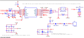
I am using ucc21710 for driving the half bridge module MOSFET half bridge module in an inverter application.

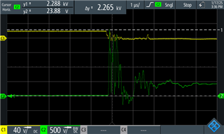
the first waveform is when we simulated a desat trigger ,the setup is made with a load (90A @400V ) connected in series with the MOSFET and connected to the DC source.

i've used a RC snubber (6ohm and 9nF) .when the gate is driven using a push button,, immediately triggering the desat  as the desat operating point is around 75A.

the Vds in channel C2 and Vgs in channel C1 is shown below.The Vds is shooting up drastically and is Vgs also gets distorted.

The second  experiment the mosfet is triggered and used to drive a load of 40A.

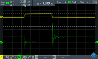
for both experiments i've included the snubber and the driver voltages are +20/-5V

the outh resistor is 8.2ohm and outl resistor is 4.7 ohm.

I've performed this test for the single phase half bridge alone .not in full bridge configuration .the aim is to test and tune the desat operating point .

Could please suggest any methods to counter the Vds spikes and distortion in Vgs

  • Hi Keviv, 

    How are you measuring the Vds and what probe were you using? It is possible a high voltage differential probe (shown below) or a probe with long ground lead can couple noise in the measurement while the noise is not actually present in the system. It's quite unlikely a 400V system would have a 2.2kV overshoot and a >1kV undershoot, so I want to make sure the probing method is correct and we're seeing real measurements. Also the small oscillation on Vgs seems normal, which makes me question whether the 2.2kV Vds ringing is actually present as well. 

    Once we confirm the above measurements actually exist in the system, I would recommend reviewing the layout as extra parasitic inductance in the high-current path can cause excessive overshoot/undershoot. We can also look into adjusting the gate resistance sizes to make turn-on/turn-off slower to dampen the spikes. Also if possible, an RC snubber can be added on Vds. 

    Thanks, 

    Vivian

  • Hi Vivian,

    One quick question ,my scope is set at  200MHz BW for all these measurements.

    Does it affect my observations.

    Thanks 

    Keviv

  • Hi Keviv,

    Due to the holiday in the US on 20th Jan 2024, many of the device experts are currently out of the office. I can answer this in the meanwhile, if your probes are rated higher BW and scope is rated for higher BW (not limited to 200MHz), it is better to capture at higher BW to be able to better signal. Below is what we recommend for capturing signal with best resolution.

    Thanks,
    Pratik