


Other Parts Discussed in Thread: MSPM0C1103,
Tool/software:
Hello,
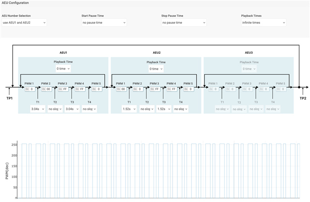
I am looking to create the below pattern as a test. But I am getting another pattern. Please help to figure out what's going wrong. Attached is I2C write and video of the pattern.
Here's the I2C write sequence from boot. Wr means I2C write, next is I2C target address (LP5810D), following which is register address and then data.
Wr 5c 0 1 -> Chip enable
Wr 5c 23 66 -> Sw reset
Wr 6c 0 1 -> Broadcast for sw issue workaround
Wr 6f 50 5
Wr 6f 50 8
Wr 6f 50 1
Wr 6f 50 3
Wr 6f 51 27
Wr 6f 50 0
Wr 6c 0 0
Wr 5c 0 1 -> Chip enable
Wr 5c 4 1 0 7 -> Enable Auto and exponential
Wr 5c d f -> Enable LOD and LSD
Wr 5c 10 55 -> Update config
Wr 5c 20 7 -> Enable LED 0,1,2
Wr 5c 50 cc 0 0 -> Set Auto DC
Wr 5c 81 1f -> Auto LED0 config for using AEU 1 and 2 for LED0
Wr 5c 84 ff ff -> PWM3 and 4 set to FF for AEU1
Wr 5c 87 a a -> PT1 and PT3 set to 3s for AEU1
Wr 5c 8c ff ff -> PWM3 and 4 set to FF for AEU2
Wr 5c 8f 7 7 -> PT1 and PT3 set to 1.5s for AEU2
Wr 5c 10 55 -> Update config
Wr 5c 11 ff -> Start pattern
Thanks, Prithvi
