


Other Parts Discussed in Thread: BQ76972, TIDA-010208, TIDA-010247
Tool/software:
To whom it may concern,
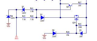
I am designing the driving circuit for multi MOSFETs circuit for BQ76972. Right now, I am following the recommendation in SLUAA09A. If my understanding is correct, in Fig. 5.2, the R45 and R40 needs to be sized large to handle the reverse charging current flow. The side effect is that it will slow down the DSG FETs turn on speed. And to increase the speed, the circuit shown in Fig. 8.21 could be adopted.
However, when I looked in to the reference design, TIDA-010208 and TIDA-010247, the driving circuit for MOSFETs is different from SLUAA09A, I am not sure if the main reason is because they are using P-MOSFET (e.g. Q28 in TIDA-010208 and Q49 in TIDA-010247) in the turn off circuit while SLUAA09A is using PNP in turn off circuit.
 V.S.
V.S.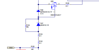
So my questions are:
1. Which driving circuit you recommended, the ones in SLUAA09A or the ones in TIDA-010208/TIDA-0101247? Or both works as expected?
2. In TIDA-010208, the R132, R133 and R135 are in the loop of reverse charging current flow. They are only 0603 footprint, and I don't think it can handle the current flow for the reverse charger connection of 16S battery.
3. In my application, I need the MOSFET to be fast turned on, and also I need reverse charger protection circuit. If I don't want a super big footprint resistor to handle the reverse charging current, I guess the only way to do that is to involve the LD pin to control a P-MOSFET as shown in SLUAA09A and TIDA-010247, is that correct?
Many thanks.
Regards,
