This thread has been locked.

If you have a related question, please click the "Ask a related question" button in the top right corner. The newly created question will be automatically linked to this question.

TLV767-Q1: Request for review of schematic of TLV76701QWDRBRQ1

Part Number: TLV767-Q1

Tool/software:

Hi, TI expert

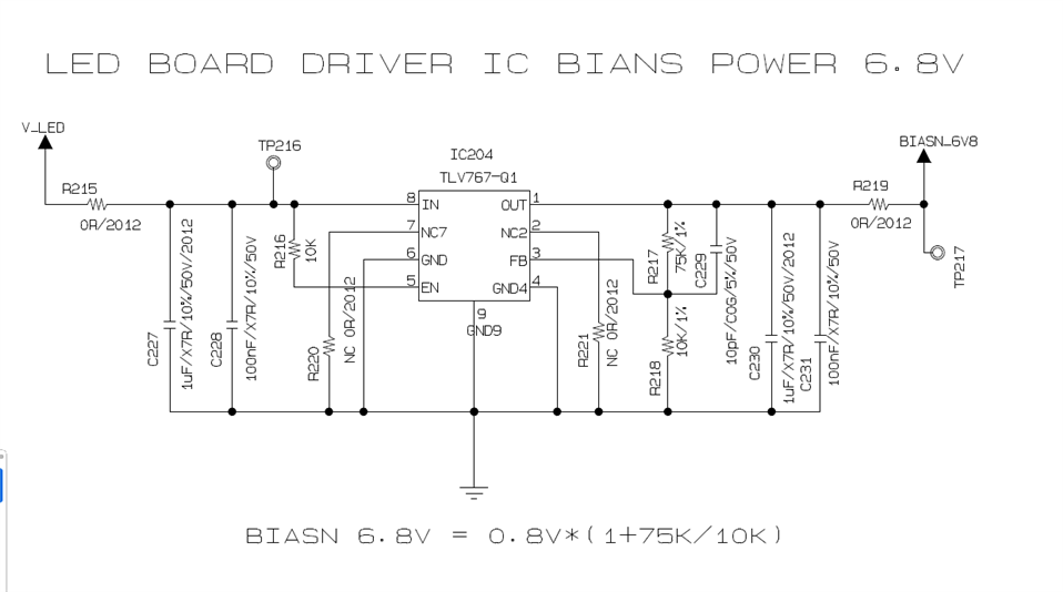
A customer has requested a schematic review of the TLV76701QWDRBRQ1.

- Application : Local-Dimming of 17-inch LCD for Vehicles

- V_LED: 12.4V applied

- OUT Voltage: 6.8V

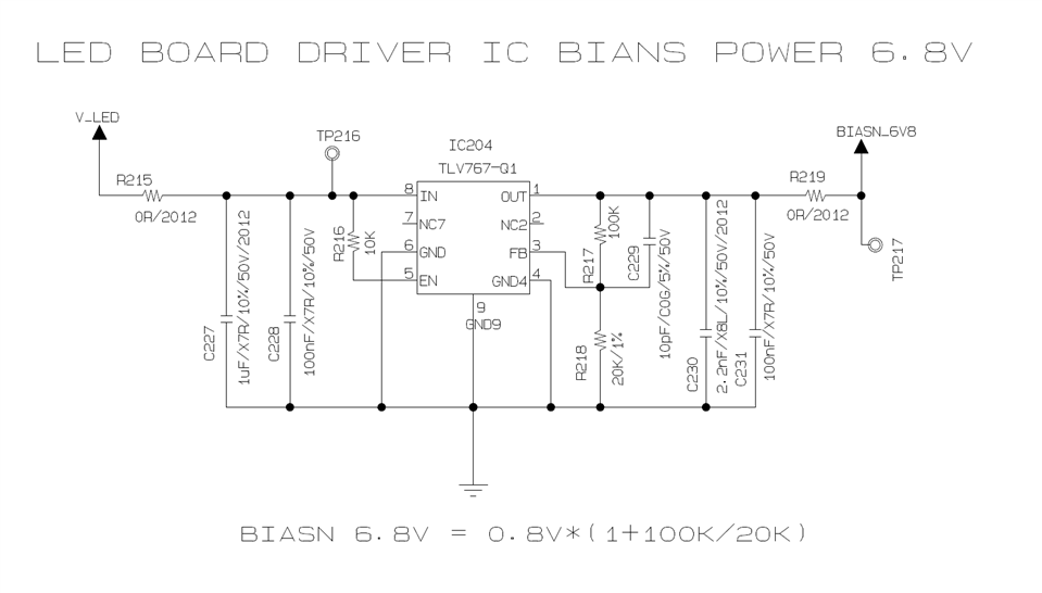
Q1) For C229, which is a Feed-Forward Capacitor (CFF), 10pF was applied with reference to the Datasheet. Can you suggest a more suitable value?

Q2) Please review whether there are any parts to be modified or added.

Please check. Thank you.

  • Hi Grady,

    Q1 - 10pF should be suitable in this use case.

    Q2 - 

    I found a few issues:

    1. The divider values are not correct for a 6.8V output. With 100kΩ and 20kΩ resistors, the output will be 0.8 * (1 + 100k/20k) = 4.8V. Replacing R218 with a 13.3kΩ resistor will  give a 6.82V output.

    2. I'd recommend increasing the output capacitance to at least 1µF for improved transient response.

    3. Pins NC2 and NC7 may optionally be grounded for better thermal performance. 

    Best Regards,

    Alex Davis

  • Hi, Alex Davis

    Thank for response.

    The customer has modified the circuit as follows based on the response.

    Please review again to see if there are any issues.

    1. 6.8V applied Ru 75k, Rl resistance 10k applied
    2. 1uF applied, time constant to be changed after future product evaluation
    3. NC2, NC7 Option resistance 0 ohm applied, additional evaluation to be scheduled

  • Hi, Alex Davis

    There has been no reply yet, please check.

    Thank you.

  • HI Grady,

    Most of the changes look fine. However, the reason we recommend connecting pins 7 and 2 to GND is to improve thermal performance of the device. Adding 0 ohm jumpers as shown will defeat this purpose. If the customer is uncomfortable connecting these pins to GND it would probably be better for their layout to leave pins 2 and 7 unconnected as in their original design. 

    Best Regards,

    Alex Davis