


Other Parts Discussed in Thread: BQ25157, BQ25190
Tool/software:
Hello,
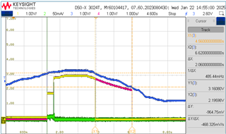
I am using the BQ25120A in a compact, portable device that has a built-in 3.7V lithium battery without an on/off switch. For this reason, and because the microcontroller used does not have a hardware reset pin, I supply the electronics via LS/LDO (operated as LS and VINLS connected to SYS) so that I can still reset the electronics by briefly turning off the LS via the control pin LSCTRL. LSCTRL is connected to the /RESET pin for this purpose and a pull-up resistor to SYS ensures that LS/LDO is always switched on together with SYS, except when a reset is manually triggered via a button connected to /MR:
I found a problem with LS/LDO which is sometimes prematurely switched off before SYS when the battery voltage (BAT) drops, even if it is still way above the BUVLO threshold.
Is there an explanation for such a behavior? According to the data sheet I would expect that LS/LDO would always follow SYS.
Let me explain in more detail:
The basic settings of the PMIC are as follows:
- V_SYS = 3.2 V
- LS/LDO = LS (no LDO, all LS_LDO_x bits are set) → V_LSLDO follows V_SYS / V_VDD
- EN_LS_LDO = 0 → LS/LDO is controlled only by the LSCTRL pin to ensure that a reset can always be triggered via /RESET (or /MR respectively).
- BUVLO = 2.6 V
Usable battery voltage range: 3.0 V – 4.2 V
The battery has an integrated protection circuit module which cuts off the cell if its voltage falls below 2.8 V.
Carrying out device tests with the above listed settings, I sometimes noticed a strange behavior of the LS/LDO output.
To get to the bottom of the problem more efficiently, I replaced the battery with a laboratory power supply to make it easier to change the V_BAT voltage. No voltage source was connected to VIN (battery only).
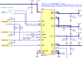
The following oscilloscope image shows the behavior of the following signals in relation to the applied battery voltage:
- CH1 (yellow): V_LSLDO
- CH2 (green): LSCTRL
- CH3 (blue): V_BAT (applied battery voltage)
- CH4 (magenta): V_SYS (V_VDD)
When increasing the battery voltage (blue), V_SYS (magenta) and V_LSLDO (yellow) switch on to 1.8 V as soon as the battery voltage crosses the default 3 V BUVLO threshold. I understand that according to Table 11 in the data sheet of the PMIC, this is an expected behavior as VIN is not valid.
During startup initialization of the device’s microcontroller, it also configures the PMIC and programs the V_SYS output to 3.2 V and BUVLO to 2.6 V.
After setting V_SYS to 3.2 V and V_BAT still rising, one can see V_SYS (magenta) trying to reach the intended higher voltage. Interestingly, V_LSLDO follows V_SYS for a very short time (not clearly visible) but then switches off completely until it is switched on again, supposedly because V_SYS finally reached the desired value of 3.2 V. This behavior is unexpected, because LSCTRL (green) always stays above the required input high threshold of 0.75 * V_SYS and I didn’t find a description in the data sheet that V_LSLDO should not follow V_SYS under these circumstances.
Then, lowering the battery voltage again, V_SYS and V_LSLDO also drop – regardless of the programmed V_SYS voltage, but remain switched on until V_BAT reaches the 2.6 V BUVLO threshold. As soon as V_BAT < BUVLO, V_SYS and V_LSLDO are switched of simultaneously as indicated in Table 11 of the data sheet.
Now, I come to the second startup sequence in the oscilloscope screen shot: V_BAT is increased quicker than the first time what seems to be the reason that V_LSLDO remains on after programming V_SYS to 3.2 V although V_SYS does not fully reach the desired level of 3.2 V (V_BAT doesn’t seem to be high enough for that).
The real disaster comes now:
All of a sudden, as V_BAT further drops, V_LSLDO is switched off while V_SYS and also LSCTRL remain switched on. V_SYS is finally also switched off but this first needs V_BAT to drop below the 2.6 V BUVLO threshold.
According to the PMIC’s data sheet one would expect that – like the first time – V_LSLDO would follow V_SYS and both supplies will switch off simultaneously when V_BAT drops below 2.6 V. However, in this case V_LSLDO switches off without any recognizable reason and the microcontroller is reset unexpectedly.
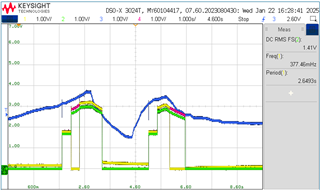
I tried some different settings like programming V_SYS to only 3.0 V instead of 3.2 V and choosing a BUVLO threshold of 2.2 V instead of 2.6 V: This, however, only changed the switching levels of the signals but not the undesired, independent switching off of the V_LSLDO output:
Don’t get confused: In this plot, CH2 (green) shows the battery current, not the LSCTRL signal.
I finally found that soft-enabling the LS/LDO solves the problem:
Interestingly, setting the bit EN_LS_LDO = 1 prevents V_LSLDO from being switched off prematurely when V_BAT drops. In this case, V_LSLDO permanently follows V_SYS until V_BAT drops below the BUVLO threshold and V_SYS / V_LSLDO are then switched off together. However, using EN_LS_LDO = 1 is not a viable solution for my device as with this, the input LSCTRL becomes inactive, and the microcontroller cannot be reset anymore in case of a hang-up. It is not clear why the behavior of LS/LDO is different depending on whether LS/LDO is operated via the LSCTRL pin or via the register bit EN_LS_LDO.
Questions:
- Is this behavior as you would expect?
- Did I miss something in the datasheet that would explain why V_LSLDO is shut down prematurely (i.e. not together with V_SYS)?
- Is there a workaround to ensure that V_LSLDO is always only switched off when V_BAT falls below the BUVLO threshold, even if LS/LDO is only controlled via LSCTRL, as intended?
- Is it normal that the voltage drop between V_BAT and V_SYS is in the range of 250 - 400 mV? It seems relatively high to me. Could this be optimized, e.g. by choosing a different 2.2 µH inductor?
- In particular, at cold temperatures, you have to expect that the battery voltage can also be less than 3.6 V due to the changed, temperature-dependent battery characteristics, and that this is still within the permissible range for the battery. In these cases, the PMIC should be able to handle the fact that V_SYS may not reach the desired programmed level and then simply be set as high as possible without an error. This seems to be the case for V_SYS, but not in every case for V_LSLDO! Do you have a comment on this?
- Are there any comparably compact PMICs that generate the output voltage via a buck-boost converter and thus are less dependent on the battery voltage?
I hope that I have explained the peculiar behavior of V_LSLDO in an understandable way and that there is a good solution to the problem.
Thank you and best regards,
Matthias

