This thread has been locked.

If you have a related question, please click the "Ask a related question" button in the top right corner. The newly created question will be automatically linked to this question.

UCC5350: Lay-Out Review for SiC FET and isolated driver and supply

Part Number: UCC5350
Other Parts Discussed in Thread: UCC14240-Q1

Tool/software:

Dear Ti,

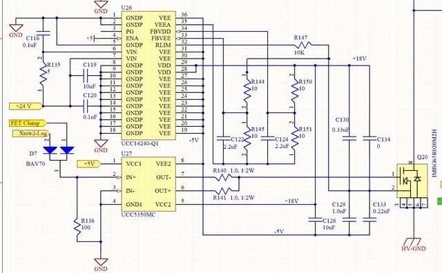
Attached is a layout for a SiC FET driven by the isolated driver and supply:  UCC5350MC and UCC14240.

Questions: I eliminated the ground plane under the driving pins, but still have a big trace for the FET Gate Common lead to connect all the capacitors.  How wide can this be, or will it create parasitic capacitance under the Gate leads.

Shall I include the Miller Clamp resistor R140, just in case, or is there no possibility for it and eliminate it?

There are still long traces for the capacitors.  Is this acceptable?

I look forward to your experienced review.

Thanks.

  • Hi Ron,

    You should use 0 ohms for the Miller turn-off resistor. There is not much benefit to removing the ground plane under the driving pins if you add 100pF of decoupling capacitance to IN+, and probably you should increase R136 to 10k, so it doesn't draw too much current. It looks like you are still working on the passive values for UCC14240-Q1.

    You should have a local 100nF decoupling capacitor between VEE2 and VCC2 to protect the output stage from transient overvoltage, but larger bulk capacitors can be further away.

    Best regards,

    Sean