This thread has been locked.

If you have a related question, please click the "Ask a related question" button in the top right corner. The newly created question will be automatically linked to this question.

BQ79606EVM-897: Cell Balancing Troubleshooting

Part Number: BQ79606EVM-897

Tool/software:

Hi,

    I have been using the BQ79606 Eval Kit to implement a battery balancer for a 6s battery pack. All is going well except I seem to be struggling to get the CB_DONE_THRESH to work correctly. Everything else seems to work as described in the data sheets as far as cell adcs, balance timers, sequencing, etc... But I am struggling to get individual cells to stop balancing when I hit my CB_DONE_THRESH. I have ensured that I am setting the enable bit on this register as well as setting a valid voltage as described here.


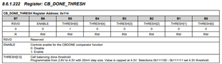
   I am setting the value with a formula similar to the following: cb_done_threshold = 0x40 + (byte)((DesiredCBDoneVoltage - 2.8f)/0.025f); where ox40 sets the enable bit for the CB_DONE comparator and the voltage relevant bits are calculated in increments of 0.025V above 2.8V as described in the above image. I feel like I have followed all the guidance in the data sheet, but I am unable to get cells to stop balancing when they reach the threshold. Balancing only terminates once the CB_CELLx_CTRL timer values have elapsed.
    Any insight on this problem would be greatly appreciated. Are there other registers that need to be set in order for this feature to work? Does the order in which you write to the relevant registers matter? Like I always set CB_DONE_THRESH before enabling cell balancing, but after setting the CB timers and duty cycle/sequencing. See code example for the registers I write to when enabling balancing. This sequence never seems to actually abort individual cell balancing when the CB_DONE_THRESH is reached, only when timer elapses. I am considering just using the UV threshold instead if I cant get this to work. Any help would be great.
Thanks,
James
Sample Code for enabling cell balancing:
  //configure cell  balancing
  WriteReg(0, CB_CONFIG, 0x0E, 1, FRMWRT_ALL_NR); // 10 minutes duty cycle, stop on fault, odds then even
  //configure cell balancing  timers
  WriteReg(0, CB_CELL1_CTRL, 0x3C, 1, FRMWRT_ALL_NR); // 60 minute balance timer
  WriteReg(0, CB_CELL2_CTRL, 0x3C, 1, FRMWRT_ALL_NR); // 60 minute balance timer
  WriteReg(0, CB_CELL3_CTRL, 0x3C, 1, FRMWRT_ALL_NR); // 60 minute balance timer
  WriteReg(0, CB_CELL4_CTRL, 0x3C, 1, FRMWRT_ALL_NR); // 60 minute balance timer
  WriteReg(0, CB_CELL5_CTRL, 0x3C, 1, FRMWRT_ALL_NR); // 60 minute balance timer
  WriteReg(0, CB_CELL6_CTRL, 0x3C, 1, FRMWRT_ALL_NR); // 60 minute balance timer
  WriteReg(0, CB_DONE_THRESHOLD, cb_done_threshold, 1, FRMWRT_ALL_NR);          // 0x40 for enable + (Vdone - 2.8) /0.025V for 4.05V = 50 = 0x32 so sum = 0x72
  WriteReg(0, CONTROL2, 0x33, 1, FRMWRT_ALL_NR);          //BAL_GO = 1, CELL_ADC_GO = 1, tsref, AUX_ADC_GO = 1
  • Hi James,

    Can you run the VCBDONE comparator through the DIAG_CTRL1[OVUV_MODE] and monitor SYS_FAULT3[CB_VDONE[ to confirm the VCBDONE is tripping properly? 

    Regards,

    David Ray

  • Thanks for the advice. So just for clarity, this is done without a battery hooked up to the balancer right? If I understand the datasheet correctly this is a built in self test that will generate a reference voltage to trip the CB_DONE comparator periodically and I will be looking for the SYS_FAULT3[CB_VDONE] bit to turn on. Currently my eval kit is getting powered by the battery itself. I will power it from a 24V bench supply instead for this test.

  • Hi James,

    Either a battery or a bench supply would work. 

    Regards,

    David Ray

  • So it appears this must be a software bug on my end. When I hook the balancer eval kit up to battery management studio and initiate a very similar balancing procedure manually through the gui, it works. I can get cells to terminate balancing at the correct CB_DONE_THRESH voltage. Something in my software must be different. I am wondering if it has anything to do with the way I set control 2 in my balance routine setup or maybe other registers I write to on startup in my code. Since I cannot see what the control2 register is set to when I write from the cell balancing tab in battery management studio (it always shows up as 0x0 in the device information box, even though i know it must be at least setting the BAL_GO bit), my CONTROL2 value in the code is my prime suspect which I am setting to 0x33. I wonder If that is the mistake on my part and I should only be setting the BAL_GO bit? Below is what my cell balancing screen looks like with CB_DONE_THRESH working.

  • Hi James,

    I recommend reading each register after you set the register to ensure that the correct information is being written into the register. If Control2 is the issue, you can try sending two separate write commands to ensure the information is correct first before sending BAL_GO.

    Regards,

    David Ray

  • So I changed a few things to closely match the config I used in the battery manager studio from my previous post. My software now behaves as the studio gui balancing does. I am now realizing that I am getting bad results even in the studio gui. For some reason I can read all cell voltages on the monitoring tab (cells 1-6), but when I try to initiate balancing with the balancing tab config in my previous post's image, cells 3-6 terminate balancing immediately in their first duty cycle, even if the CB_DONE_THRESHOLD is far below the cell voltage. It will however balance cells 1 and 2 correctly and terminates up reaching the CB_DONE_THRESHOLD voltage. Am I missing something in my gui setup for all 6 cells to properly balance?

  • Hi James,

    I recommend running the VCBDONE BIST to confirm that the IC is not damaged on cells3-6.

    Regards,

    David Ray