This thread has been locked.

If you have a related question, please click the "Ask a related question" button in the top right corner. The newly created question will be automatically linked to this question.

LM22672MR-ADJ enable pin problem when configured to operate in inverting mode

I am using a two LM22672MR-ADJ. One to generate a +16V supply, the other to generate a -16V supply. Both converters are powered from the same +24V supply rail. They are both synced from an external clock running at 768Khz.


When I leave the enable pin floating they both start up fine and run perfectly, however in the overall design of the system I need to delay the startup of the converters until the 24 volt rail reaches 18 volts or more.


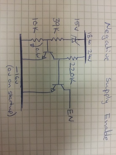
When I connect a resistor voltage divider to each enable (with a 5V zener to protect the enable pin from any chance of over voltage) I find that the LM22672MR-ADJ used in the +16V converter starts up fine, but the LM22672MR-ADJ used in the -16V supply will only start up successfully about 50% of the time.


The topology I have implemented is basically what is suggested in the datasheet on page 15.

http://www.national.com/ds/LM/LM22672.pdf

Obviously, since I am going for a different output voltage and running at a different frequency my component choices are different.


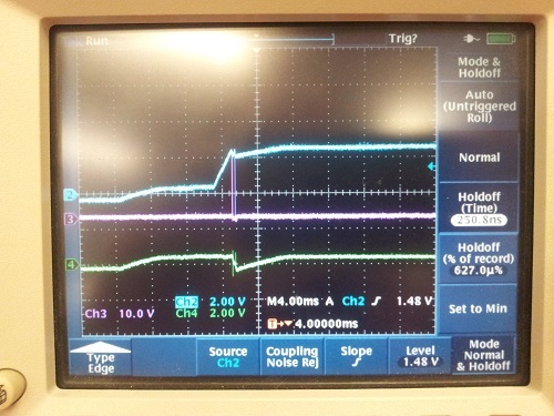
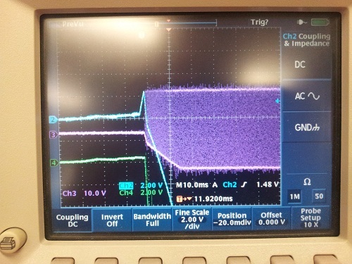
I have noticed that when the -16V converter starts up, its "ground" which becomes the -16V output actually goes positive relative to true ground because of the diode in the circuit. Is this potentially causing a problem with the feedback? The only thing I can think of is that adding the enable resistors (between Vin, EN and GND (aka -16V) is altering the feedback network and causing the converter to sometimes fail on startup.


How do people normally use the enable pin for this chip when it is configured for this inverting mode?


  • Blue Trace = Enable Pin

    Purple Trace = Switching Pin

    Green Trace = Output Voltage (during operation this should be -16volts)


    This is what it is doing when it is not starting properly


    This is what it is doing when it is starting correctly

  • There are possibly two issues that can be causing the problem.

    1) If you have dual rail loading on the +/- 16V output rails such as op amps or power amps or the like; Then it is possible for those loads to pull the -Vout line slightly positive and cause proper start-up of the negative rail to occasionally fail. We suggest placing a reverse biased schottky between ground and the -16V output rail to clamp this condition and allow proper start-up. (anode to -16V and cathode to ground) This is probably the problem, but also consider the following:

    2) Since we don't have access to your  schematic of the implementation of the enable of the negative rail let us direct you to AN-2027 (originally from NSC) which suggests several circuits to effectively drive the enable pin of a conventional buck used in the buck-boost inverting configuration.

    One possible configuration is to use the 18V input supervisory voltage divider on the positive switcher Enable input only. (UVLO control of +16V.) Then use the simple PNP level shifter shown in Figure 3 of AN-2027 as the enable control of the -16V inverting stage, driving this stages enable input from the +16V output rather than from a divider on +24Vin. There may be a need to adjust resistor values of figure 3. This configuration will only slightly delay the turn-on of the negative rail.

    If you need further help you can contact me directly.

    Alan Martin      alan.martin@ti.com


  • Hi Alan,

    Thanks for the suggestions.

    I have decided to approach it from a different angle. Instead of driving the enable pin high when I want to turn the converter on, I have decided to pull the enable low until it is OK to turn on. This seems to work perfectly.

    Below is the circuit I have used. Threshold at room temperature is 17.95 volts.