This thread has been locked.

If you have a related question, please click the "Ask a related question" button in the top right corner. The newly created question will be automatically linked to this question.

TPS65987D: PD Source enable until VSAFE5 i reached

Part Number: TPS65987D
Other Parts Discussed in Thread: TPS25751, BQ25730, TPS55288, , TPS65987, , TPS25730

Tool/software:

Hello,

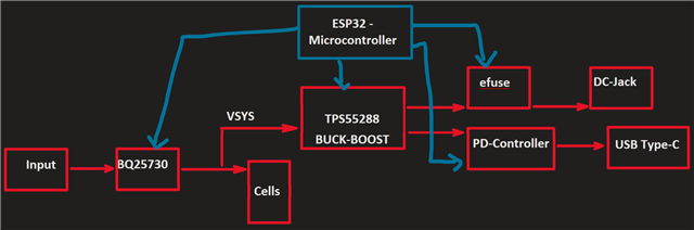
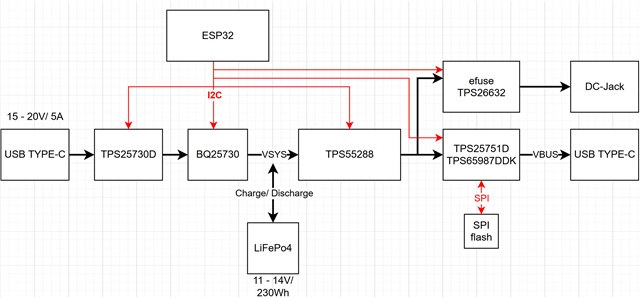
I am currently working on a power bank design that utilizes the TPS65987D as a power source, capable of delivering up to 100W. My design features two outputs: a USB PD source as the primary output and a DC-Jack as the secondary output. To ensure only one output is active at a time, an eFuse is used to control the on/off switching of the DC-Jack output.

To guarantee that VSAFE5V is always available on the USB Type-C port—and to prevent any unintended voltage from being applied due to a prior setting from the DC-Jack output—I am looking for a solution.

Is it possible to achieve this by using a microcontroller or through manual control to switch the PD controller on/off or place it into a sleep mode until the VSAFE5V is guaranteed at PPHV1,2?

Thank you!

  • Hi Ali,

    If you do not require DP alt mode, we are currently suggesting you switch to the TPS25751.

    For both devices, you have a couple options.

    1. I2C control: Disable the "TypeC State machine" in the Port Configuration register with an I2C write. This will disable port negotiation for the device.
    2. GPIO Control: Both devices support "Fault_Input_Event" as one of the configurable gpio events that can be mapped to any of the GPIOs on the device. This event will disable the port and make the CC-line pins HI-Z, effecting preventing PD negotiation. 

    Those previous options are specific to disabling the port when the PD controller in is a functional operating mode.

    (3) If you are specifically worried about sourcing when PPHV/5V is not present, but are ok sinking power during this time, you can start with a device configuration of sink only, and then update the port power role types when 5V is ready using I2C writes to registers.

    (4) Depending on your system architecture, you may also be able to limit the port activity by not powering or programming the port. If you are powering through internal power only (Vin3V3f) and not supporting dead battery boot, you can choose not to provide the VIN3V3 voltage until you are ready to boot the PD controller.

    Thanks and Regards,

    Chris

  • Hi Chris,

    Thank you for your response.

    In my design, I have separated the input and output, and I need to ensure PTM compliance. For this reason, I am not using the OTG feature, and the PD cannot be directly connected to the BQ25730 charge controller that I am using to charge my cells. Instead, I am generating the negotiated PDO using VSYS through a second buck-boost converter. The PD is configured to operate in a source-only mode.

    A second output is implemented to provide the customer with the option of delivering voltage/current through a DC jack. However, only one output can be active at a time. The entire system is managed by an ESP32 microcontroller.

    I selected the TPS65987D based on a recommendation from one of your colleagues. However, I see that the TPS25751 should be directly connected to the BQ charge controller if I want to source power higher than 5V, but it can only function as a DRP or sink.

    The issue I previously described is the following: I need to ensure that whenever a cable is connected, VSAFE5V is always delivered first—before any prior PDO or other output—until the negotiation process takes place.

    How would you suggest achieving this behavior?

    This a simple block-diagram of my design

    Best regards,
    Ali

  • Hi Ali,

    What is "PTM compliance"? I'm not familiar with this.

    Instead, I am generating the negotiated PDO using VSYS through a second buck-boost converter. The PD is configured to operate in a source-only mode.

    Understood, the first input generates a rail, and the output voltage for the PD controller is generated off of the TPS55288.

    The TPS25751 may be capable of supporting that in the future, but as you mentioned, it currently does not support that. Do realize that the TPS65987DDK will not be able to support the latest compliance.

    The issue I previously described is the following: I need to ensure that whenever a cable is connected, VSAFE5V is always delivered first—before any prior PDO or other output—until the negotiation process takes place.

    How would you suggest achieving this behavior?

    As mentioned in the first response, you need some way to disable the port or the ic entirely until you are confident VSAFE5V comes up, and then you can enable said port or IC.

    The recommended controls are shared in the first response. You can use those to prevent the port from connecting while you are waiting for VSAFE5V.

    Thanks and Regards,

    Chris

  • Hi Chris,
    Thank you for your response. sorry for the misunderstanding.

    I need my power bank to support an attached device either from the battery, from a connected input, or from both simultaneously. However, I am considering one of the solutions you suggested, such as disabling the "Type-C State Machine" in the Port Configuration register via I2C.

    I have few questions:

    1. Is it possible to configure the GPIOs of the TPS25751D to provide information about the negotiated PDO? This way, I could use this data to set the output through the MCU via I2C by adjusting the TPS55288’s output accordingly.
    2. Do you have any recommendations for a PD controller that supports up to 100W and can be used without a charge controller?
    3. In the attached document from TI, you can see that the TPS65987D is directly connected to the TPS55288, setting the output via I2C. I am looking for a similar configuration, but with an MCU acting as an intermediary between both ICs. Do you think it is possible to achieve the same configuration using the TPS25751D instead?
      USB Type C Power Delivery Source with TPS65987D and tps55288.pdf

    Looking forward to your response!

  • Hi Ali,

    I need my power bank to support an attached device either from the battery, from a connected input, or from both simultaneously. However, I am considering one of the solutions you suggested, such as disabling the "Type-C State Machine" in the Port Configuration register via I2C.

    Oh, interesting. The PD controller itself does not seem to be managing the input power, so this should be fine?

    Is it possible to configure the GPIOs of the TPS25751D to provide information about the negotiated PDO? This way, I could use this data to set the output through the MCU via I2C by adjusting the TPS55288’s output accordingly.

    We have gpios that assert when a specific source PDO is negotiated, but that may not be the best solution here. In the TRM, check the GPIO events for "SourcePDOXContract". When configuring the device, you assign specific voltages and power levels to unique PDOs in the Transmit Source Capabilities register. A typical configuration is PDO1 -> 5V, PDO2->9V, PDO3->15V. When the contract is negotiated, that GPIO will assert.

    Another option would be to read from status registers over I2C when you know a contract has been negotiated. When a contract is negotaited, the Active Contract RDO register should update with the active PDO, allowing you to read the PDO from an I2C host to determine the voltage and current that needs to be provided.

    Do you have any recommendations for a PD controller that supports up to 100W and can be used without a charge controller?

    Both the TPS65987DDK and TPS25751 are capable of doing it, but currently only the TPS65987DDK support sourcing up to 100-W without a charge controller. For the 987, you have a couple options for PD -> DC-DC control for sourcing. (1) GPIOs (see 987EVM as an example, (2) I2C table on PD configured to write to 55288 directly, and (3) reading status register and using interrupts to program the 55288 from and EC.

    n the attached document from TI, you can see that the TPS65987D is directly connected to the TPS55288, setting the output via I2C. I am looking for a similar configuration, but with an MCU acting as an intermediary between both ICs. Do you think it is possible to achieve the same configuration using the TPS25751D instead?

    For now you should probably stick with the TPS65987 if you want to source higher voltages. It is possible but the TPS25751 is not ready to support that just yet.

    Thanks and Regards,

    Chris

  • Hi Chris,

    Oh, interesting. The PD controller itself does not seem to be managing the input power, so this should be fine?

    AT the input i am using the tps25730D sink only to manage the input.

    Both the TPS65987DDK and TPS25751 are capable of doing it, but currently only the TPS65987DDK support sourcing up to 100-W without a charge controller. For the 987, you have a couple options for PD -> DC-DC control for sourcing. (1) GPIOs (see 987EVM as an example, (2) I2C table on PD configured to write to 55288 directly, and (3) reading status register and using interrupts to program the 55288 from and EC.

    I checked the storage availability, and it seems that the TPS65987DDK is rarely available. I believe that both the TPS65987D and TPS65987DDJ are also capable of handling this functionality. However, I am still considering the TPS25751D as an option since I can configure the Interrupt Event for I2Ct_IRQ/Interrupt Mask for I2C1 to toggle whenever a new contract as a provider is negotiated. Alternatively, I could use the GPIOs, which, as you mentioned, is the same method for both PD controllers.

    That being said, I have a few questions:

    1. If I am using an Embedded Controller (EC) on board to manage power by adjusting the buck-boost converter, is it still relevant to fill out the sections related to the BQ charge controller and charging current in the GUI questionnaire?
    2. How reliable is the switching behavior of the internal sourcing path when the TPS25751D is not controlling any BQ charge controller, but instead, the EC is adjusting the voltage?
      • In section 8.3.3.2 of the datasheet, it is mentioned that "The TPS25751D senses the PPHV and VBUS voltages to control the gate voltages to enable or disable the FETs."
      • Is this sensing mechanism still available when the PD is acting as a source?
    3. Given this configuration, where the PD controller, EC, and buck-boost converter work together, do you think the system will meet the settling time requirements specified in the USB PD specification whenever a new contract is negotiated?

    I appreciate your insights on this and look forward to your feedback.

    Best regards,
    Ali


  • Hi Ali,

    AT the input i am using the tps25730D sink only to manage the input.

    Yes, that is an important clarification, I thought you had a BQ25730 on the input? Or is there both? I'm a little confused with the input stage now, could you clarify?

    I checked the storage availability, and it seems that the TPS65987DDK is rarely available. I believe that both the TPS65987D and TPS65987DDJ are also capable of handling this functionality. However, I am still considering the TPS25751D as an option since I can configure the Interrupt Event for I2Ct_IRQ/Interrupt Mask for I2C1 to toggle whenever a new contract as a provider is negotiated. Alternatively, I could use the GPIOs, which, as you mentioned, is the same method for both PD controllers.

    Understood. I would recommend for the TPS25751 or TPS65987DDK to be the most viable here, as they are the latest in their family and have most of the current support. TPS65987DH may work, but just know it is an older part. I would not recommend the TPS65987DDJ, the part was intended for specific use cases  (TBT reference designs) and the resources for that device are all locked behind the design.

    If I am using an Embedded Controller (EC) on board to manage power by adjusting the buck-boost converter, is it still relevant to fill out the sections related to the BQ charge controller and charging current in the GUI questionnaire?

    No, in fact, you should leave those empty and should not choose one of the configs that contain a BQ device. Choosing a BQ config and answering those questions will enable and configure the PD to send I2C messages on the I2Cc line to an expected BQ device, programming config and functional registers during run time. If you are not using a BQ charge controller in this setup, this could potentially add issues.

    How reliable is the switching behavior of the internal sourcing path when the TPS25751D is not controlling any BQ charge controller, but instead, the EC is adjusting the voltage?
    • In section 8.3.3.2 of the datasheet, it is mentioned that "The TPS25751D senses the PPHV and VBUS voltages to control the gate voltages to enable or disable the FETs."
    • Is this sensing mechanism still available when the PD is acting as a source?

    We have seen a couple customers use this to some success, but internally and with EVMs we typically test the TPS25751 with I2C and with BQ converters.

    Yes, there is some functional and protection related voltage sensing when acting as a source.

    Part of the PD protocol requires the source to send a PSRDY when it is ready to provide a negotiated power contract. A step during this process is for the PD to check the voltage to make sure it reflects the contract.

    Given this configuration, where the PD controller, EC, and buck-boost converter work together, do you think the system will meet the settling time requirements specified in the USB PD specification whenever a new contract is negotiated?

    It can, but will require some effort. If you check the PD spec, there is a section on source transition timings. I think you have between 35 and 325 ms to transition the voltage. See section 7.3 of the PD spec.

    Thanks and Regards,

    Chris

  • Hi Chris,

    Yes, that is an important clarification, I thought you had a BQ25730 on the input? Or is there both? I'm a little confused with the input stage now, could you clarify?

    My setup includes a Sink-only PD controller (TPS25730D) managing the input of the charge controller (BQ25730). The MCU adjusts the registers of the BQ25730, such as input voltage and current, based on the negotiated PDO (15V or 20V / 3A or 5A). After that, I use VSYS to generate the voltage for the PD source at the output.

    Please refer to my diagram for a complete overview of my design.

    Understood. I would recommend for the TPS25751 or TPS65987DDK to be the most viable here, as they are the latest in their family and have most of the current support. TPS65987DH may work, but just know it is an older part. I would not recommend the TPS65987DDJ, the part was intended for specific use cases  (TBT reference designs) and the resources for that device are all locked behind the design.

    This is very helpful, thank you! Do both PD controllers provide interrupt features via GPIOs? Since this method is much easier and less complex than overwhelming the I²C bus.

    No, in fact, you should leave those empty and should not choose one of the configs that contain a BQ device. Choosing a BQ config and answering those questions will enable and configure the PD to send I2C messages on the I2Cc line to an expected BQ device, programming config and functional registers during run time. If you are not using a BQ charge controller in this setup, this could potentially add issues.

    so if i'm using the TPS25751D i should leave the questions empty like this:

    Yes, there is some functional and protection related voltage sensing when acting as a source.

    So if I understand correctly, when a cable is plugged into the USB Type-C port and the PPHV voltage is higher than 5V, the PD controller will not start negotiation or enable switching between PPHV and VBUS until it detects 5V on the PPHV side. Only after that, it can provide power to VBUS.

    Thanks and Regards,
    Ali

  • Hi Ali

    My setup includes a Sink-only PD controller (TPS25730D) managing the input of the charge controller (BQ25730). The MCU adjusts the registers of the BQ25730, such as input voltage and current, based on the negotiated PDO (15V or 20V / 3A or 5A). After that, I use VSYS to generate the voltage for the PD source at the output.

    Please refer to my diagram for a complete overview of my design.

    Thanks for the updated block diagram, this makes more sense.

    Do realize that the TPS25730 is much more limited in configuration and ability that the TPS25751 or TPS65987. It is a sink only PD controller that is configured through resistive dividers. It should be a good choice for the port if it is power sink only and does not require too much configuration or complexity.

    This is very helpful, thank you! Do both PD controllers provide interrupt features via GPIOs? Since this method is much easier and less complex than overwhelming the I²C bus.

    I'm not sure what you mean by interrupt via GPIO. You can check the TRM of both devices to see what GPIOs are supported in the "GPIO events" section.

    Both can support I2C interrupt configurability as well.

    so if i'm using the TPS25751D i should leave the questions empty like this:

    No, you may need a slightly custom project for this.

    You can start with the 5-V only config for testing, but you would essentially need a source only config that does not support sinking on the HV path. Correct me if I'm wrong, but the TPS25751 is planned to be source only?

    When you select this config, the BQ settings will be grayed out.

    The end result of using the App Customization tool is to be able to generate a binary using the Export->Generate .... feature in the top right of the GUI. If the options are grayed out for generation, this indicates that the questionnaire has not been fully filled out. 

    If the BQ questions are not grayed out and still configurable, this means you are still using a config that will send the BQ I2C messages. To avoid this, select a configuration from q1 that does not have a BQ device in the diagram.

    So if I understand correctly, when a cable is plugged into the USB Type-C port and the PPHV voltage is higher than 5V, the PD controller will not start negotiation or enable switching between PPHV and VBUS until it detects 5V on the PPHV side. Only after that, it can provide power to VBUS.

    Kind of, yes. What happens is you will configure the PD controller through the binary image to advertise a set of Source PDOs (different voltage and power combinations).

    On initial connection to a USB-C PD sink device, our PD controller first enters a default type-c contract, which is a 5-V only contract. For the TPS25751 we need 5-V on both the PP5V and PPHV for proper source operation.

    Once in the default, PD communication can start and the source will advertise the Source PDOs. Through negotiation, the Sink will request and the source will accept a specific PDO. (i.e. Sink requests a 15V 3A contract that was one of the PDOs offered by the source, and the source will send an accept message).

    At this step, the Source PD controller (TPS25751 or TPS65987) will indicate that the source voltage needs to transition to a new value. This could be a GPIO or an I2C interrupt as mentioned before. At this step, we would expect the system to increase the supplied voltage from 5-V to 15-V.

    The PD controller will be sensing the PPHV side to make sure the voltage transitions to the correct value, and sends the confirmation PS_RDY message when ready.

    Thanks and Regards,

    Chris