This thread has been locked.

If you have a related question, please click the "Ask a related question" button in the top right corner. The newly created question will be automatically linked to this question.

LM5160: Latched shutdown

Part Number: LM5160

Tool/software:

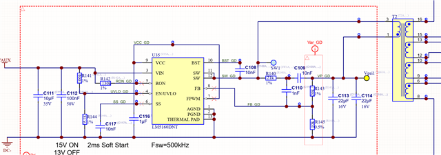
We have a flybuck design using the LM5160 exhibiting a strange shutdown behavior. To my knowledge, we've only seen it on one board so far and it is difficult to probe with a scope, but below are the static conditions measured with multimeter in the shutdown condition. The supply shuts down somewhat randomly and stays off until power is cycled.

Vin: 17V

EN/UVLO: 1.6V

VCC: 0V

Vpri1: 0V

IC temp: 30C

So it seems the VCC regulator is shut down which as I understand the datasheet should only occur with UVLO pin below 0.35V, which it is not close to, or thermal shutdown, which is not happening and should reset itself anyway. Anything we should look at? Damaged IC?

Thanks

  • Hello Benjamin,

    Can you fill out the calculator spreadsheet in the product folder with your specification so i can check design against the recommended values.

    Thanks.

    David.

  • Hi David. I'm not sure how that is necessary for my question but I suppose it's standard procedure. Here is the sheet. Everything seems pretty well in line to me. The ripple circuit is a bit off (I think our values may have been pulled from a ref design without much thought) but this doesn't seem relevant to the issue we're seeing.5037.LM5160FBKQuickStartCalculator - FinalVersion.xls

  • Hello Benjamin,

    Appreciate you filling this out.  It actually helps me to see what you are testing.  It looks like your VOUTpri= 6V and you need an 19V on the output, this requires a relatively large step up turns ratio.  Personally, I don't recommend great that 1:2.5 from Primary to secondary.  Looks like you have higher turns ratio than this.  So my suspicion is focused on the transformer.  What transformer are you using?  What is the leakage inductance.  if too high, that can wreak havoc on stability due to large negative currents reflected from Secondary back to the primary.  Also, I would defiantly adjust Rr to the recommended value, but I am not sure this will resolve your issue.  please follow the Rr guideline in the spreadsheet.  Finally What rectifying Diodes are you using?  Thanks.

    Looking forward to your response.

    David.

  • Hi David. Rectifying diodes are SMD1150PL-TP.

    Transformer is custom. Turns ratio is 1:3.28. Leakage inductance is spec'd at 350nH max but I can check what the actual measured values are for the parts we have. 

  • Hello Benjamin,

    What is your Lprimary?  Are you sure you have enough Gap length and the core is not saturating?  

    Thanks,

    David.

  • Lprimary is 12uH. I will loop in the magnetics engineer to address the other questions. I really didn't expect this to become a transformer investigation. While these are obviously important details for the supply performance I don't see how they explain the chip being shut down with the VCC regulator disabled. 

  • David, We're no where near saturation during normal operation.  Lp=12uH.  At peak current of 1.9A the flux density is around 0.18T using Ae.  At the max current limit of 2.5A the flux density is around 0.31T, and that's using Amin not Ae.  The AL=250nH/T^2 which is the smallest, standard gap size for the EP13 core we are using.  Our parts are DC bias tested by the supplier to check for possible saturation issues.  We're using Ferroxcube 3F36 materials and switching at 500kHz.  Anything else?

  • Just checking every issue it may be Ian.

    Thanks for confirming.  

    David.

  • Hello Benjamin,

    It could be hitting current limit, and the output voltage goes low.  When you say the chip shuts down, can you be more specific.  Is it switching when it "Shuts down"?  Is the device dead?  Is the part getting hot?  Can you take some scope shots if the device is still switching?  Thanks.

    David.

  • David. As I mentioned early when it is shut down, the VCC is 0V and the part is not hot. I have not actually seen this issue in person and am relying on a colleague to report it but it seems to me that it must not be switching if the VCC regulator is down. Scoping will be difficult but we'll try to get better measurements when we can.

  • Benjamin,

    If you swap out the device, does it work again?  If we are dealing with a device that has been damaged, it hard to find out root cause without understanding what the supply is doing when it failed?  Start up?  Load step?  High Temp?  Scope shots are definitely very helpful  Thanks.

    David.

  • David, swapping out the device may be the next step. Keep in mind that it does function properly after a power cycle and will keep running for an indeterminate time before shutting off again.

  • Hello Benejamin,

    For now, we can assume that the device is working then.  So, the task here is to try to capture some waveforms when the converter is running.

    please can you measure primary switch voltage for me when the primary and secondary are loaded, or in a condition before you observe shutdown, thanks.

    David.