Other Parts Discussed in Thread: TIDA-050026-23881
Tool/software:
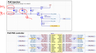
For a 6-Port PoE+ application I've used the TPS23881 as PSE controller.
The circuit used is based on the TIDA-050026-23881 reference design, schematics are shown below.

ETH_CX_A goes to the centre tab of ethernet pair A and ETH_CX_B goes to the centre tab of ethernet pair B on the magnetics.
When using this circuit, the following occurs:
- The PoE power is on instantly
- Voltage on ETH_CX_A: 48V
- Voltage on ETH_CX_B: 0.55V
- No class negotiation occurs
- PoE_GATE remains 0V at all times (with respect to POE_KSENS, which is connected to the PoE GND)
The only parts connected to this circuit that are not shown in the image are the Bob Smith termination circuit (there's a DC blocking cap between the different centre tabs) and the magnetics.
I suspected there might've been something wrong with the MOSFET Q500, the footprint matches and it wasn't mounted in reverse or shorted.
When it is removed, the situation changes into the following:
- PoE class negotiation is now done properly on PoE_DRAIN
- PoE_GATE is subsequently driven high
- Without the MOSFET, there's no power output on the ethernet connector
I've measured the removed MOSFET to see if there was something wrong with them, but drain to source measured 0.55V (using the diode setting) and source to drain measured open loop as expected.
The 0.55V on ETH_CX_B (when the MOSFET is still on the board) suggests to me there's a diode bridge bypassing the MOSFET somewhere, but measuring the MOSFET itself when removed shows no sign of it nor does the rest of the circuit.
How is it possible the PoE output is on without the MOSFET being driven?