Tool/software:
Hi,
I just got 10 PCBA using the TPS62177 coupled with the inductor IFSC1515AHER100M01. This inductor is recommended in the datasheet and it has no polarity.
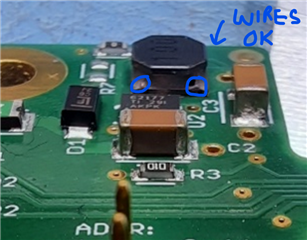
The inductor has 100 stamped on it and when compared to the wiring side, it might be one way or the other. So, the inductors might be oriented differently in the same T&R (180º from one to another).
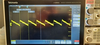
When the inductor wires are oriented toward the TPS62177, the output ripple at 10mA load (which is the typical and static load) is around 22mV.
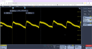
When the inductor wires are 180º (not facing the IC), the output ripple is around 122mV. 100mV more in this orientation.
I got 3 boards with the inductor wiring facing the IC and 7 boards at 180º ... The behavior is constant for all boards, 3 PCBs at 20mV ripple and 7 PCBs at 120mV ripple.
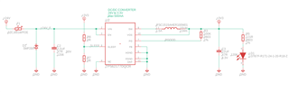
Here is the schematic (R7 is not installed)
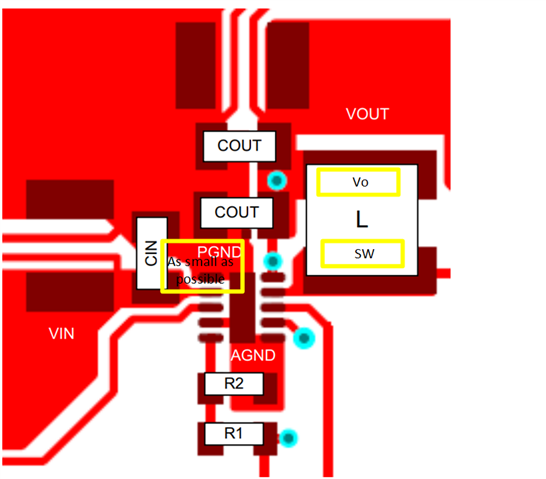
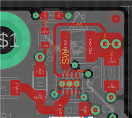
PCB is a 4 layer (Top / GND plane / Power plane (3.3V) / Bottom):
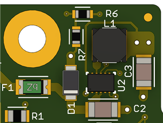
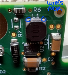
Inductor in low ripple orientation:
Inductor in high ripple orientation:
Is it normal to get this behavior ? Am I missing something ?
Should I be specifying to the CM about the inductor orientation (which is almost impossible I think...) ?
Have you tested another inductor which would not be orientation dependant for proper behavior ?
Thanks for your help !