Other Parts Discussed in Thread: TPS65994, TPS65994QFNEVM, TPS25751
Tool/software:
Team,
is it possible to power-up from USB-C only (Dead-Battery-Mode), enable USB PD PHY and request 20V@5A (100W).
Ideal would be without any EEPROM connected to the TPS65994AD. Is there any GPIO which indicates if 20V are available?
We want to enable the System DC/DC converters with that signal.
Since we plan to have a system with two USB-C ports, in a later stage the host controller would reconfigure the second TPS65994 port to be a power sourcing device.
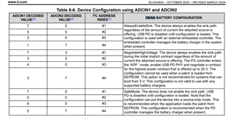
Looking at the datasheet I have difficulties understanding the configuration that is marked in yellow
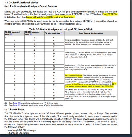
If we don't add any I2C EEPROM to the TPS65994, does it negotiate 20V in NegotiateHighVoltage mode?
Because 8.4.1 says the TPS is waiting for an EC to load a config in case no EEPROM is detected.
Thanks!